An uplink transmission method and device

A transmission method and technology of network equipment, applied in the field of uplink transmission method and equipment, can solve the problem of no transmission scheme and the like

Active Publication Date: 2017-06-13
DATANG MOBILE COMM EQUIP CO LTD
View PDF8 Cites 0 Cited by
  • Summary
  • Abstract
  • Description
  • Claims
  • Application Information

AI Technical Summary

Problems solved by technology

However, the terminal only supports single-band transmission capability in the uplink. When it is necessary to perform uplink transmission on uplink carriers of different frequency bands, there is no corresponding transmission scheme.

Method used


Image

  • An uplink transmission method and device
  • An uplink transmission method and device
  • An uplink transmission method and device

Examples


Embodiment Construction

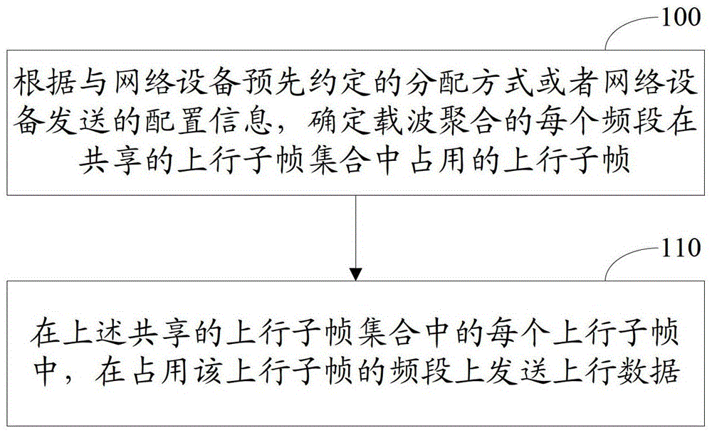
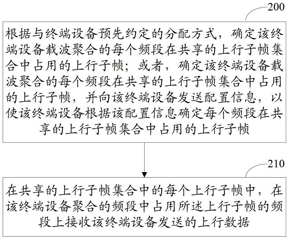
[0025] The technical solution provided by the embodiment of the present invention allocates uplink subframes in the shared uplink subframe set for each frequency band of carrier aggregation, so as to ensure that uplink data is only sent on one frequency band in one uplink subframe, through time division multiplexing The method realizes sending uplink data to different network devices in different frequency bands, and realizes uplink transmission of terminal devices that only have single-band sending capability in the uplink under the Inter-band CA scenario. In the embodiment of the present invention, carrier aggregation means that in one downlink subframe, a terminal can simultaneously receive downlink data on multiple frequency bands, and in one uplink subframe, a terminal can only send uplink data on one frequency band.

[0026] The technical solutions provided by the embodiments of the present invention will be described in detail below in conjunction with the accompanying d...


PUM


Abstract

The invention discloses an uplink transmission method and equipment. The method on the terminal device side includes: according to an allocation method pre-agreed with the network device or configuration information sent by the network device, determining the uplink subframes occupied by each frequency band of the carrier aggregation in the shared uplink subframe set, wherein each frequency band The occupied uplink subframes are different from each other, and the shared uplink subframe set is the set of uplink subframes with the same subframe number in the frame structure used in each frequency band; on each uplink subframe in the shared uplink subframe set , the uplink data is sent using the frequency band that occupies the uplink subframe. The technical solution provided by the embodiments of the present invention allocates uplink subframes in the shared uplink subframe set for each frequency band, ensures that uplink data is sent on one frequency band in one uplink subframe, and realizes uplink in the Inter-band CA scenario Uplink transmission for terminals with only single-band transmission capability.

Description

technical field [0001] The present invention relates to the field of communication technology, in particular to an uplink transmission method and equipment. Background technique [0002] With the evolution of technology and the increase of data services, in subsequent versions of the Long Term Evolution-Advance (LTE-A, Long Term Evolution-Advance) system, the following carrier aggregation (CA, CarrierAggregation) scenarios may exist: [0003] The carrier (or cell) on which the terminal performs CA uses different frequency band (band) resources, that is, Inter-band CA. The frame structure used by the terminal in different frequency bands may be the same or different. For example, the terminal uses a frequency division duplex (FDD, Frequency Division Duplex) frame structure on each carrier in different frequency bands, or the terminal uses each carrier in different frequency bands. All carriers use a Time Division Duplex (TDD, Time Division Duplex) frame structure (the TDD up...

Claims


Application Information

Patent Timeline
Patent Type & Authority Patents(China)
IPC IPC(8): H04L1/00H04L1/06
CPCH04L1/00H04L1/06H04L5/001
Inventor 高雪娟潘学明
Owner DATANG MOBILE COMM EQUIP CO LTD
Why Eureka
Try Eureka