Physical uplink sharing channel transmission method, uplink scheduling method and device

A technology of physical uplink sharing and transmission method, which is applied in the field of mobile communication and can solve problems such as increased delay and inability to transmit

Inactive Publication Date: 2014-10-15
BEIJING SAMSUNG TELECOM R&D CENT +1
View PDF0 Cites 12 Cited by
  • Summary
  • Abstract
  • Description
  • Claims
  • Application Information

AI Technical Summary

Problems solved by technology

If the SIB uplink and downlink configuration of the cell is not 10ms PUSCH RTT (Round Trip Time) uplink and downlink configuration, but the number of uplink subframes in the actual downlink configuration of the cell is far less than the SIB uplink and downlink configuration (for example, the SIB uplink and downlink configuration is TDD Uplink and downlink configuration #0, but in fact the downlink configuration is TDD uplink and downlink configuration #2), the HARQ process of the uplink PUSCH of the backward UE in the cell will not be transmitted because it is scheduled to the downlink subframe, and the uplink P...

Method used


Image

  • Physical uplink sharing channel transmission method, uplink scheduling method and device
  • Physical uplink sharing channel transmission method, uplink scheduling method and device
  • Physical uplink sharing channel transmission method, uplink scheduling method and device

Examples


Embodiment 1

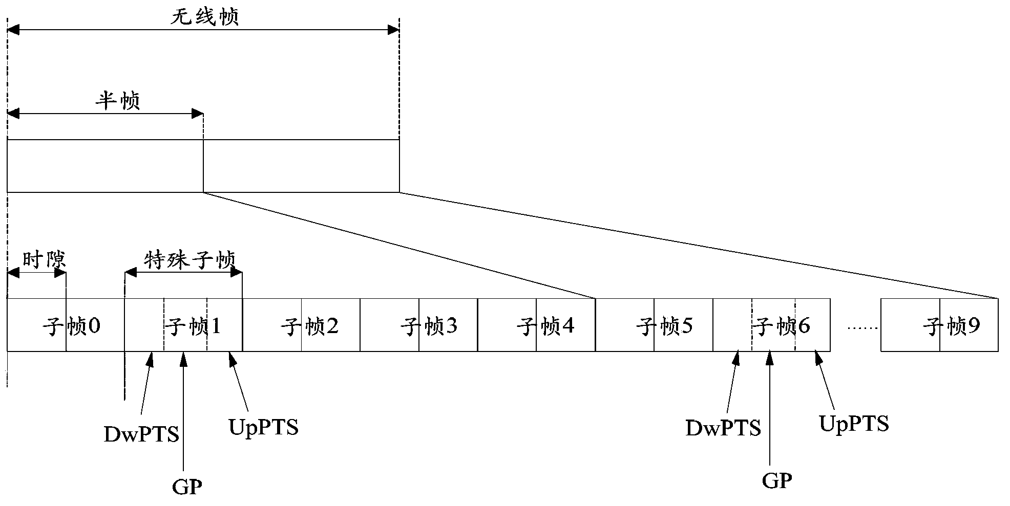
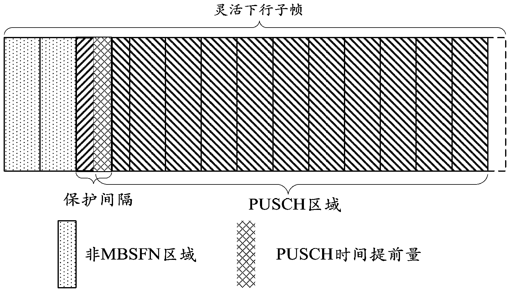
[0117] Assuming that the SIB uplink and downlink configuration of the flexible TDD reconfiguration cell is TDD uplink and downlink configuration #1, when working in the flexible TDD reconfiguration state, the subframe #4 and subframe #9 of each radio frame are configured as MBSFN subframes, then , subframe #4 and subframe #9 are flexible downlink subframes, subframe #3, subframe #7 and subframe #8 are flexible subframes, and the specific steps of the uplink scheduling method in this embodiment are as follows:

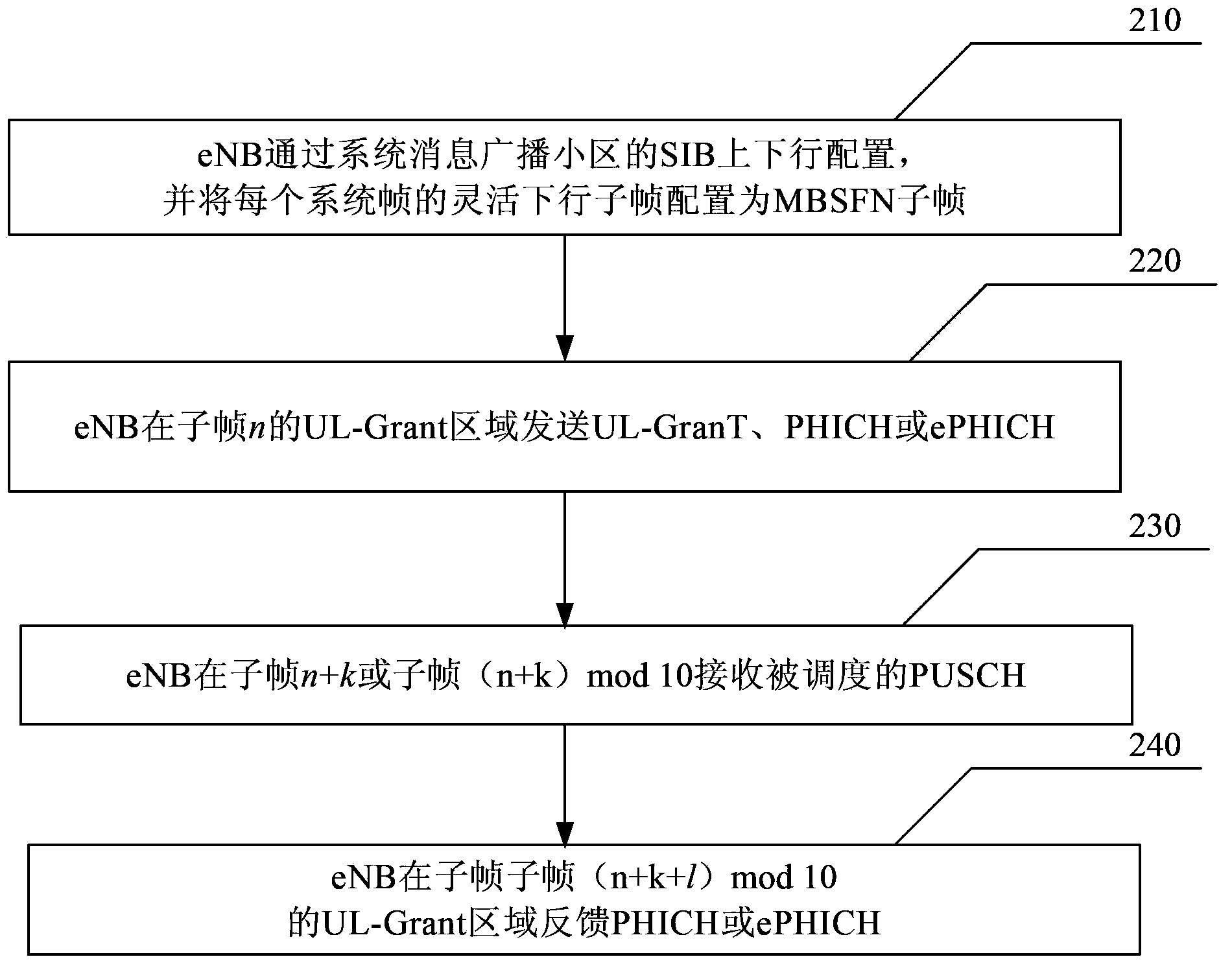
[0118] S101: The eNB broadcasts the current SIB uplink and downlink configuration as TDD uplink and downlink configuration #1 through system messages, and configures subframe #4 and subframe #9 of each radio frame as MBSFN subframes through system messages.

[0119] S102: The UE acquires the current SIB uplink and downlink configuration and MBSFN subframe configuration information of the cell by receiving the system information sent by the eNB.

[0120] S103: The eNB se...

Embodiment 2

[0134] Assume that the SIB uplink and downlink configuration of the flexible TDD reconfiguration cell is TDD uplink and downlink configuration #2, and when working in the flexible TDD reconfiguration state, configure subframe #3 and subframe #8 of each radio frame as MBSFN subframes, subframes Frame #7 is a flexible subframe, and the specific steps of the uplink scheduling method in this embodiment are as follows:

[0135] S201: The eNB broadcasts the current SIB uplink and downlink configuration as uplink and downlink configuration #2 through system messages, and configures subframe #3 and subframe #8 of each radio frame as MBSFN subframes through system messages.

[0136] S202: The UE acquires the current SIB uplink and downlink configuration and MBSFN subframe configuration information of the cell by receiving the system information sent by the eNB.

[0137] S203: The eNB sends an uplink scheduling instruction UL-Grant, PHICH or ePHICH in the UL-Grant area of ​​subframe n. ...


PUM


Abstract

The invention discloses a physical uplink sharing channel transmission method comprising steps of retaining a fixed UL-Grant area in a downlink in the process of the TDD uplink-downlink configuration which is dynamically changing and receiving uplink scheduling orders and transmitting PUSCH by UE according to a PUSCH synchronization HARQ timing relationship of a 10ms RTT. The invention solves the conversion problem of the PUSCH synchronizing HARQ timing relationship on the TDD uplink and downlink configuration conversion point in the process of the TDD dynamically resetting the configuration and solves the problem that the HARQ progress delay of the PUSCH is increased which is caused by the backward UE. Besides, the above scheme that the invention puts forward has a small alteration on the present system, which doesn't affect the compatibility of the system, and realizes the simplicity and high efficiency.

Description

technical field [0001] The present application relates to the technical field of mobile communication, and in particular, the present application relates to a transmission method of a physical uplink shared channel, a method and equipment for uplink scheduling. Background technique [0002] Long Term Evolution (LTE, Long Term Evolution) technology supports frequency division duplexing (FDD, Frequency Division Duplexing) and time division duplexing (TDD, Time Division Duplexing) two duplexing modes. figure 1 It is a schematic diagram of the frame structure of the TDD system of LTE. The length of each wireless frame is 10 milliseconds (ms), and it is equally divided into two half-frames with a length of 5ms. Each half-frame contains 8 time slots with a length of 0.5ms and 3 special fields. The length is 1ms, and the 3 special domains are downlink pilot time slot (DwPTS, Downlink pilot time slot), guard interval (GP, Guard period) and uplink pilot time slot (UpPTS, Uplink pilo...

Claims


Application Information

Patent Timeline
IPC IPC(8): H04L1/18H04W72/12
Inventor 张世昌李迎阳孙程君
Owner BEIJING SAMSUNG TELECOM R&D CENT
Why Eureka
Try Eureka