Sanitary fitting

A technology for sanitary equipment and accessories, applied in mechanical equipment, engine components, valve devices, etc., can solve difficulties and other problems, and achieve the effect of comfortable operation

Active Publication Date: 2014-10-15
HANSA METALLWERKE AG
View PDF5 Cites 3 Cited by
  • Summary
  • Abstract
  • Description
  • Claims
  • Application Information

AI Technical Summary

Problems solved by technology

In this functional principle a seal with a large diameter is required, which tends to cause difficulties
This, together with possible lateral forces from the sprinkler hose, tends to render the automatic reset ineffective after shutting off the water flow

Method used


Image

  • Sanitary fitting
  • Sanitary fitting
  • Sanitary fitting

Examples


Embodiment Construction

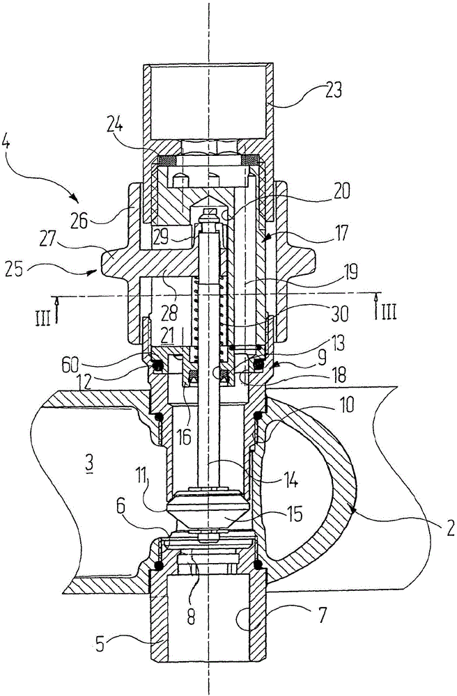
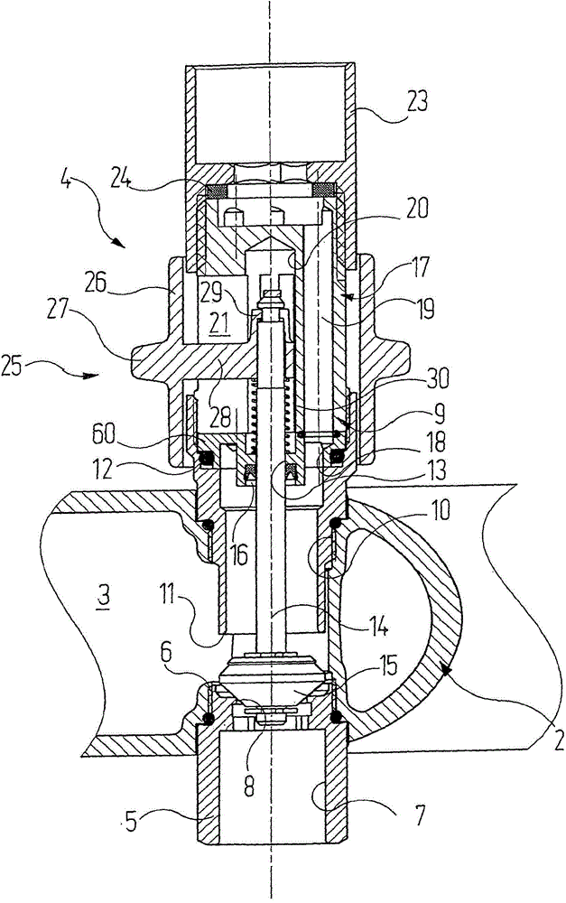
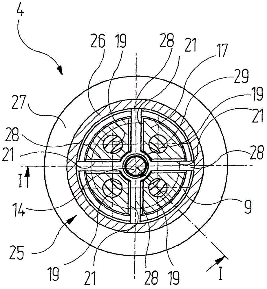
[0038] First refer to Figures 1 to 3 . There, a region of the housing 2 of the sanitary fitting is shown partially cut away. The types of plumbing fittings are in this example the same as below by means of Figures 4 to 9 The described embodiment is the same. It suffices to point out here that a water inflow chamber 3 is formed inside the housing 2 , via which water from, for example, a mixing valve or a thermostatic valve is conveyed to a switching device generally designated by the reference numeral 4 . The water flowing in through the water inflow chamber 3 can be guided selectively to one of the two water outlets by means of the switching device 4 .

[0039] In the exemplary embodiment shown, the first water outlet is formed by a pipe connection / connection sleeve 5 which is screwed into a threaded hole 6 of the housing 2 from below. The pipe connection 5 can be connected, for example, to a hose of a hand sprinkler. A first valve seat 8 is formed in the inner hole 7 h...


PUM


Abstract

The invention relates to a sanitary fitting comprising in a known manner a housing (2) with two water outlets (5, 9, 23), at least one (9, 23) of said outlets being tubular. A switching device (4) allows the water flow to be conducted from a water inlet area (3) formed in the housing (2) to one of the two water outlets (5, 9, 23) in a selective manner. The switching device comprises an actuating element (25) with a sleeve-shaped region (26) which is movably guided on the outer lateral face of the tubular water outlet (9, 23) in an axial direction. A device (28, 29) is used to transmit a movement of the sleeve-shaped region (26) of the actuating element (25) to a double valve cone (15) which is part of the switching device (4). This type of switching device (4) is particularly comfortable to handle and easy to operate for the user.

Description

technical field [0001] The invention relates to a sanitary equipment fitting, which has [0002] a) a housing in which a water inflow chamber is formed, [0003] b) two water outlets, at least one of which is designed as a tube and protrudes from the housing, [0004] c) a switching device by which the flow of water from the water inlet chamber of the housing can be selectively directed to one of the two water outlets, the switching device comprising: [0005] ca) a double valve cone, which closes the first valve seat in the water path leading to the first water outlet in the first end position, and closes the second valve seat in the water path leading to the second water outlet in the second end position. seat; [0006] cb) a valve stem connected to the double valve cone; [0007] cc) a manually operable actuating mechanism, by means of which the valve stem and thus the double valve cone can be moved in the axial direction. Background technique [0008] A large number...

Claims


Application Information

Patent Timeline
Patent Type & Authority Applications(China)
IPC IPC(8): F16K11/044
CPCF16K11/0445
Inventor B·阿森马赫尔
Owner HANSA METALLWERKE AG
Why Eureka
Try Eureka