Assembly and method for transferring rod-shaped items for the tobacco processing industry from a sender unit to a receiver unit
A technology of a sending unit and a receiving unit, which is applied in the field of device of rod-shaped products, can solve the problems of energy consumption and unfavorable product protection.
- Summary
- Abstract
- Description
- Claims
- Application Information
AI Technical Summary
Problems solved by technology
Method used
Image

Examples
Embodiment Construction
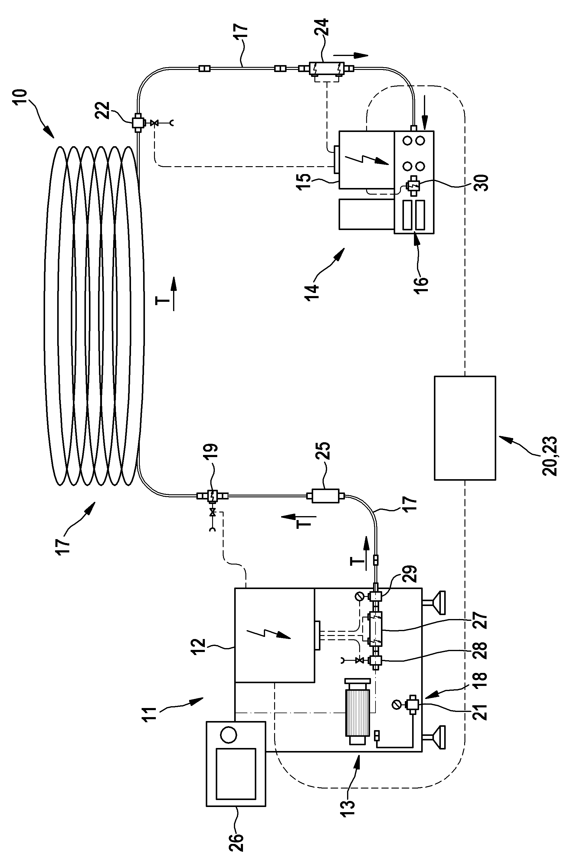
[0035] The invention is illustrated with the aid of a device for feeding filter rods from a filter rod production machine to a filter rod assembly machine. The invention of course also relates to all devices for sending (alternatively also described as transfer, launch, transport, etc.) rod-shaped products of the tobacco processing industry from a sending unit to a receiving unit, wherein the sending can be via a single line or via Several lines are completed, wherein in the latter case there is a corresponding number of transmitter modules and receiver modules.
[0036] The device 10 shown in the figure is constructed and arranged for the transfer of rod-shaped products for the tobacco processing industry and a sending unit 11 comprising at least one belt control mechanism 12 and at least one sending module 13 for sending the products along the transport direction T, At least one receiving unit 14 with a control mechanism 15 and at least one receiving module 16 for receiving ...
PUM
 Abstract
Description
Claims
Application Information
PatSnap Eureka turns technology decisions into work you can execute. Powered by our Innovation Knowledge Graph, it runs expert workflows across engineering, life sciences, materials and intellectual property. Get your review-ready output in minutes.


