Display device for displaying a system state

a display device and system state technology, applied in the direction of static indicating devices, simultaneous indication of multiple variables, instruments, etc., can solve the problem that users can frequently not perceive the displayed information optimally

Inactive Publication Date: 2010-03-25
SIEMENS AG
View PDF4 Cites 7 Cited by
  • Summary
  • Abstract
  • Description
  • Claims
  • Application Information

AI Technical Summary

Benefits of technology

[0006]An object of the invention is therefore to specify a display device for displaying a system state, by means of which a user is better able to take in the displayed information.
[0011]It is also particularly advantageous if the processing of the information comprises an adjustment of the information density displayed, so that the information density is maximized for a short viewing distance and the information density is reduced for a long viewing distance.
[0013]The approach of the user to the sensor is interpreted here so to speak as a request for detailed information from the display device, like the natural process of “closer viewing”. In the case of an average, regular viewing distance it is thus possible in a simple manner to display a clear display that is “not overloaded”, with additional information only being automatically added as the user approaches the display device. This is particularly advantageous in areas of application where manual interaction with the display device is not desired or possible, for example in a sterile environment during a medical operation in an operating theater.
[0022]In this process the volume can be increased for example, when the user moves away from the display device. It is also possible to lower the tone level, when the distance between the user and the display device increases, as lower tones can be perceived more readily than high ones at a longer distance. However this is also a function of the acoustic characteristics of the environment of the display device, so that higher tones may be more effective as the distance increases, due to resonance effects for example.
[0028]The display device ensures that the information can be identified in a wide range of distances between a user and the display device. The resulting display of information is clear and appropriate to requirements. The user can interact in a contactless manner with the display device by varying the viewing distance. Automatic activation of escalation mechanisms is also possible, if important information cannot be perceived due to too great a viewing distance (the extreme instance being when the user is absent).

Problems solved by technology

If the distance between the display device and the user is variable, the user can frequently not perceive the displayed information optimally.

Method used


Image

  • Display device for displaying a system state
  • Display device for displaying a system state

Examples


Embodiment Construction

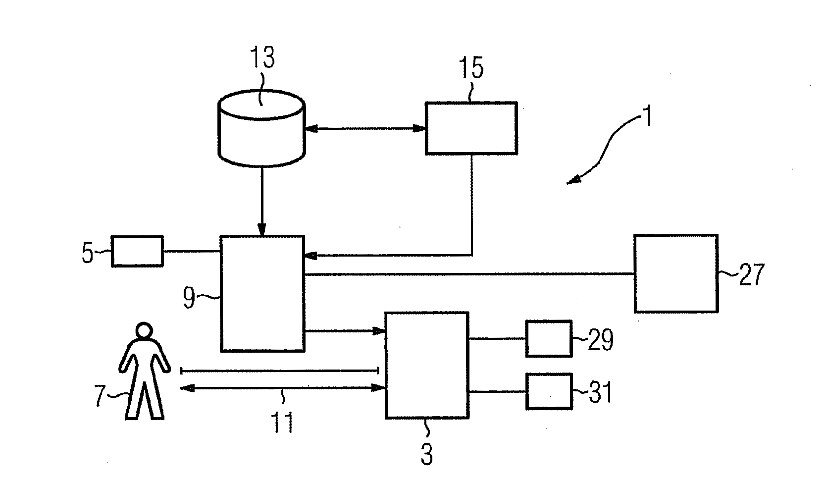
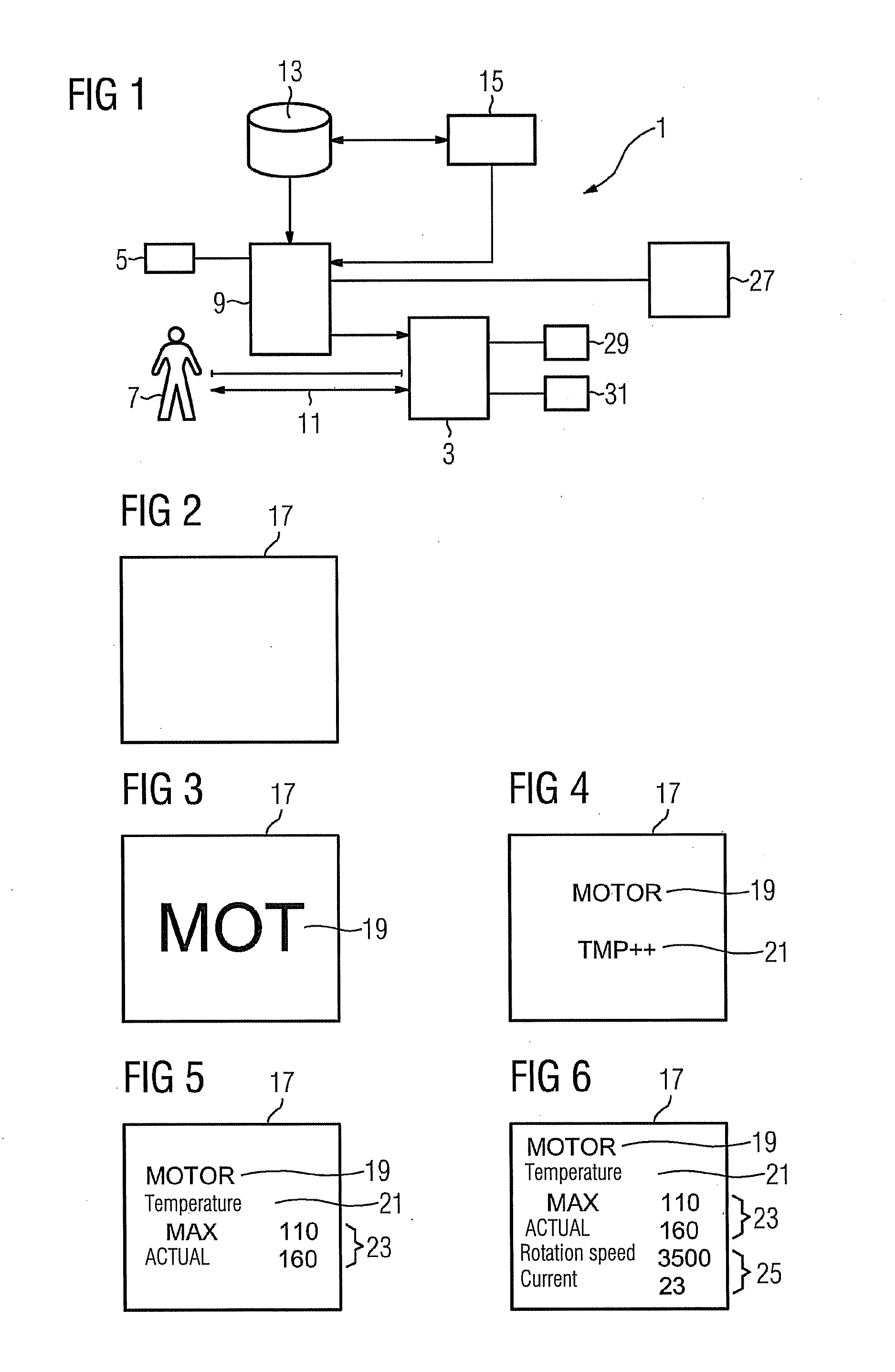
[0033]A display device 1 comprises an output unit 3, a sensor 5 for determining a distance 11 between a user 7 and the output unit 3 and a control unit 9 for adjusting the reproduction of the information on the output unit 3. If the user 7 moves away from the output unit 3, as determined by the sensor 5, the reproduction of the information characterizing the system state on the output unit 3 is adjusted, for example by reducing the information density of the information for reproduction on the output unit 3. Conversely the information density can be increased, when the user 7 approaches the output unit 3.

[0034]As well as a visual display of the information, an acoustic reproduction of the information is alternatively or additionally possible, for example on the output unit 3 and / or on a further output unit 27. In the present example the output unit 3 comprises both a display unit 29 for the graphic reproduction of the information and also a loudspeaker 31 for simultaneous or alterna...


PUM


Abstract

A display device for displaying a system state has an output unit for reproduction of information characteristic of the system state, a sensor for detecting a distance between a user of the display device and the output unit, and a control unit for processing the reproduction of the information in the output unit as a function of the detected distance.

Description

CROSS REFERENCE TO RELATED APPLICATIONS[0001]This application is the US National Stage of International Application No. PCT / EP2007 / 062973 filed Nov. 29, 2007 and claims the benefit thereof. The International Application claims the benefits of German Patent Application No. 10 2006 057 097.9 DE filed Dec. 4, 2006, both of the applications are incorporated by reference herein in their entirety.FIELD OF INVENTION[0002]The invention relates to a display device for displaying a system state, it being intended for a current system state of a technical system connected to the display device to be displayed on the display device.BACKGROUND OF INVENTION[0003]In a plurality of technical systems, for example in industrial systems or medical systems, measured variables that occur or variables derived therefrom are displayed in order to display a current system state. The term system state here is intended also to include for example measured physiological data of a patient recorded using a medic...

Claims


Application Information

Patent Timeline
Patent Type & Authority Applications(United States)
IPC IPC(8): G09G5/00H04R1/02G06F3/048G06F3/0481
CPCG01D7/02G06F3/0481G06F2203/04806G09G2340/14G09G5/36G09G2320/0261G09G2320/10G09F19/00G01D2207/30
Inventor BERTSCH, RUDIGER
Owner SIEMENS AG
Why Eureka
Try Eureka