Angle steel right-angle profile cutting method and angle steel right-angle profile cutting method

A technology of right-angle profiles and cutting methods, which is applied to workshop equipment, manufacturing tools, etc., can solve problems such as the phenomenon of opening angles, easy openings, and errors, and achieve the effect of improving precision

Active Publication Date: 2016-01-20
STATE GRID CORP OF CHINA +1
View PDF5 Cites 0 Cited by
  • Summary
  • Abstract
  • Description
  • Claims
  • Application Information

AI Technical Summary

Problems solved by technology

However, after the two angle steels are marked and cut, they are prone to opening at the joint line (that is, there is a splicing gap), such as figure 2 As shown, there is a gap of 10mm in the largest place
Even if the method of enlarging the sample is adopted, it is not easy to draw a precise blanking and cutting line. On the one hand, it may consume a lot of man-hours. On the other hand, if there is a little carelessness in the whole process of enlarging the sample, errors will occur. There may also be a phenomenon of opening angle (that is, the angle at the joint of two angle steels is greater than 90 degrees), such as image 3 shown

Method used


Image

  • Angle steel right-angle profile cutting method and angle steel right-angle profile cutting method
  • Angle steel right-angle profile cutting method and angle steel right-angle profile cutting method
  • Angle steel right-angle profile cutting method and angle steel right-angle profile cutting method

Examples


Embodiment Construction

[0023] Exemplary embodiments of the present disclosure will be described in more detail below with reference to the accompanying drawings. Although exemplary embodiments of the present disclosure are shown in the drawings, it should be understood that the present disclosure may be embodied in various forms and should not be limited by the embodiments set forth herein. Rather, these embodiments are provided for more thorough understanding of the present disclosure and to fully convey the scope of the present disclosure to those skilled in the art.

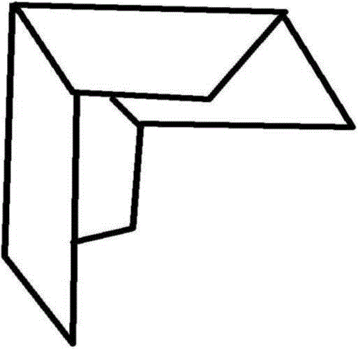
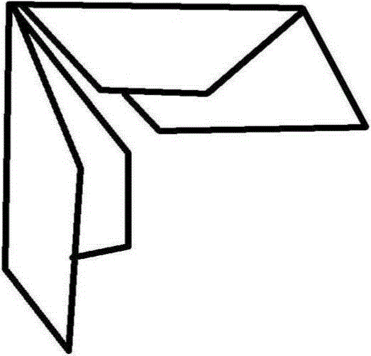
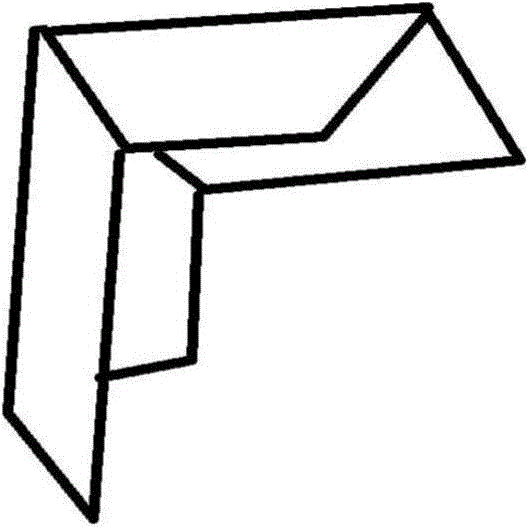
[0024]In the following embodiments of the present invention, angle steel is mainly used as an example to illustrate the method for blanking and scribing angle steel right-angle profiles and the method for cutting angle steel right-angle profiles of the present invention, but the present invention is not limited to angle steel, and can be used for angle steel Right-angle profiles of other materials, such as aluminum alloy, plastic st...


PUM


Abstract

The invention discloses a method for feeding and scribing angle steel. The method includes scribing a straight line AM perpendicular to a ridge line of the angle steel in a plane of a first straight plane of the angle steel and near end sides of the angle steel; taking a point M' on the straight line AM; drawing a straight line M'K passing the point M' to be parallel to the ridge line of the angle steel; taking the point M' as a first start point, taking the length / 0.5a on the straight line M'K in the direction away from the end side of the angle steel, acquiring the point N', wherein the a is the length of the AM'; connecting the point A and the point N' by a straight line and extending the straight line to a sideline of the first straight plane to obtain an intersection point N of the straight line AN' and an end line, opposite to the ridge line, of the first straight plane of the angle steel, namely a first cutting point, wherein the AN is a first cutting line; acquiring a second cutting point L and a second cutting line AL of a second straight plane of the angle steel by the same method. Via the method, feeding and cutting lines of the angle steel can be quickly scribed.

Description

technical field [0001] The invention relates to the field of angle steel processing, in particular to a method for blanking and marking angle steel right-angle profiles and a method for cutting angle steel right-angle profiles. Background technique [0002] In practice, it is usually necessary to fasten the ends of two angle steel-type right-angle profiles of a certain specification to form a 90-degree frame with the right-angle back facing outward. like figure 1 As shown, it shows the situation when the ends of two angle steels of a certain specification (for example, the side length is 30mm) are snapped together to form a 90-degree frame with the right-angle back facing outward. However, after the two angle steels are cut with a scribe line, they are prone to opening at the joint line (that is, there is a splicing gap), such as figure 2 As shown, there is a gap of 10mm in the largest place. Even if the method of enlarging the sample is adopted, it is not easy to draw a...

Claims


Application Information

Patent Timeline
Patent Type & Authority Patents(China)
IPC IPC(8): B25H7/00
Inventor 张勇张万利郝广科张中胡琼王梅程奕梅李京欣
Owner STATE GRID CORP OF CHINA
Why Eureka
Try Eureka