Drain pump

A technology for drainage pumps and vanes, which is applied in the direction of pumps, axial flow pumps, pump components, etc., and can solve problems such as noise, rotation balance deterioration, and vibration

Active Publication Date: 2014-10-22
FUJIKOKI MFG CO LTD
View PDF7 Cites 3 Cited by
  • Summary
  • Abstract
  • Description
  • Claims
  • Application Information

AI Technical Summary

Problems solved by technology

[0008] However, the blade shape shown in Patent Document 1 poses a problem in the injection moldability of the rotary blade, and the wall thickness is not uniform during injection molding, and the rotation balance is deteriorated, causing noise and vibration problems.

Method used


Image

  • Drain pump
  • Drain pump
  • Drain pump

Examples


Embodiment Construction

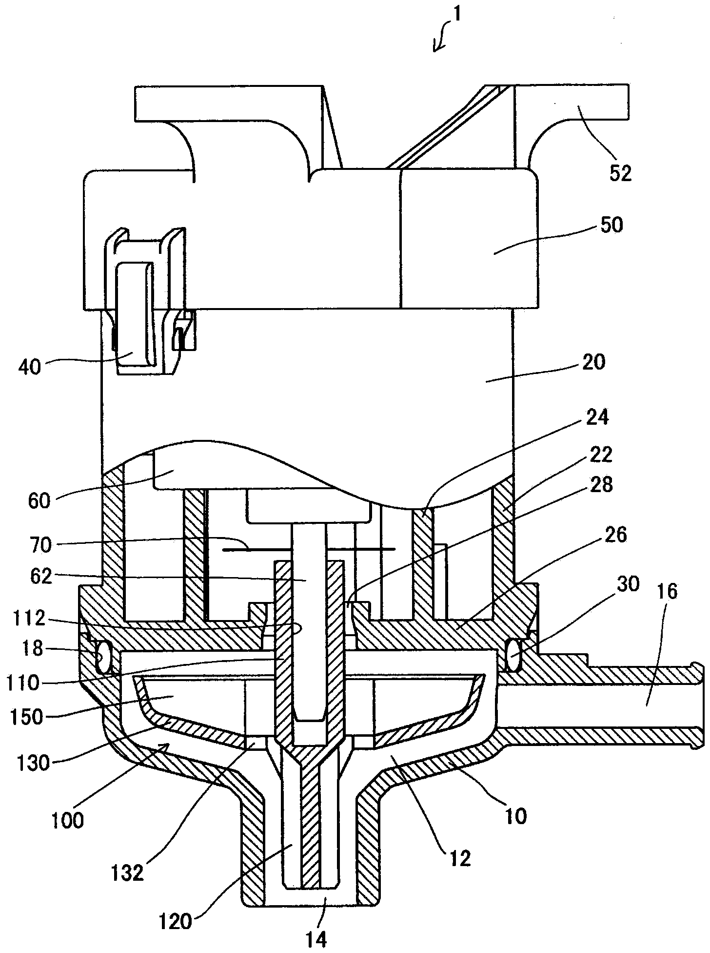
[0036] figure 1 A drain pump according to one embodiment of the present invention is shown.

[0037] The drain pump 1 has a resin casing 10 , and the casing 10 has a suction port 14 and a discharge port 16 communicating with a pump chamber 12 . The cover portion 26 of the cover body 20 is fitted into the housing 10 by a snap-fit ​​mechanism.

[0038] The cover body 20 has an outer cylindrical portion 22 and an inner cylindrical portion 24 , and a bracket 50 is attached to the upper portion of the cover body 20 via a locking portion 40 . The bracket 50 has an attachment portion 52 for attaching the drain pump 1 to other equipment.

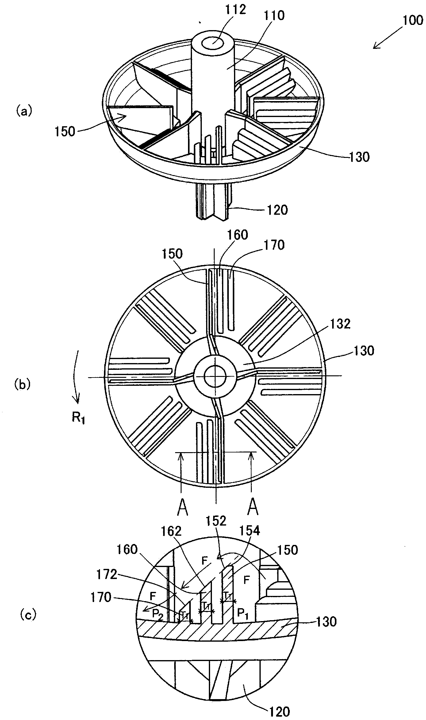
[0039] The inner cylinder portion 24 of the cover 20 supports the motor 60, and the drive shaft 62 of the motor 60 is inserted into the insertion hole 112 of the mounting shaft 110 of the rotary blade 100, thereby supporting the rotary blade 100, which is arranged on Inside the pump chamber 12 of the casing 10 . The mounting shaft 110 of the rot...


PUM


Abstract

A rotating blade (100) comprises a large-diameter blade (150), a small-diameter blade (120) and an annular member (130) and rotates in the direction of an arrow (R1). The rear side of the large-diameter blade (150) is provided with a first large-diameter auxiliary blade (160) and a second large-diameter auxiliary blade (170). The upper surfaces (152, 162, 172) of the large-diameter blade (150), the first large-diameter auxiliary blade (160) and the second large-diameter auxiliary blade (170) are set to become lower and lower. Water (F) flows smoothly, so that the generation of vortex cavitation can be prevented. According to the invention, the vibration and the noise of the rotating blade of a drain pump mounted on an air conditioner can be reduced.

Description

technical field [0001] In particular, the present invention relates to a drain pump installed in an air conditioner. Background technique [0002] In the indoor unit of the air conditioner, moisture in the air condenses and adheres to the heat exchanger during the cooling operation, and the water drops fall into the water collecting pan provided below the heat exchanger. In order to drain the water accumulated in the water collecting pan to the outdoors, a drain pump is attached to the indoor unit. As an example of such a drainage pump, rotating blades are rotatably provided in a casing, the casing is provided with a suction port at the lower end and a discharge port is provided at the side, and the rotating blades are rotated by a motor, and the motor passes through the cover. fixed to the upper opening of the housing. When the motor is driven to rotate the rotating vane, the drain water stored in the water collecting pan is sucked from the suction port, drawn up along th...

Claims


Application Information

Patent Timeline
IPC IPC(8): F04D29/24F04D29/66
CPCF04D3/00F04D29/66
Inventor 佐藤永加藤友也
Owner FUJIKOKI MFG CO LTD
Why Eureka
Try Eureka