Electric connector

A technology of electrical connectors and connectors, which is applied in the direction of connections, circuits, parts of connection devices, etc., can solve problems such as inability to cope, and achieve the effect of increasing the installation strength and expanding the range

Active Publication Date: 2014-10-22
HIROSE ELECTRIC GROUP
View PDF5 Cites 13 Cited by
  • Summary
  • Abstract
  • Description
  • Claims
  • Application Information

AI Technical Summary

Problems solved by technology

In other words, when the receptacle connector has a locking portion on the outer surface of the peripheral wall, it cannot cope with
[0009] Furthermore, even in the case where the plug connector is accepted inside the receiving portion of the receptacle connector, it is assumed that there are a plurality of locked portions simultaneously with the locking metal piece of the plug connector due to displacement in one direction in the terminal arrangement direction. In the case of a receptacle connector in the form of a locking metal fitting that engages, since the plurality of locking parts of the receptacle connector are displaced in the same direction when locking, one engaging protrusion respectively provided on the two end walls The plug connector of Patent Document 1, which protrudes toward opposite sides, cannot be used for mating with the above-mentioned receptacle connector.

Method used


Image

  • Electric connector
  • Electric connector
  • Electric connector

Examples


no. 1 approach >

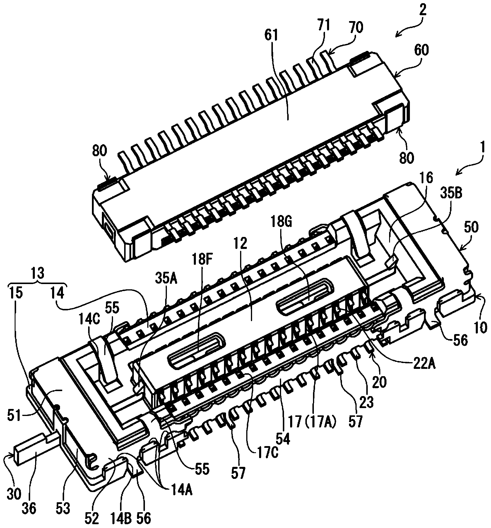
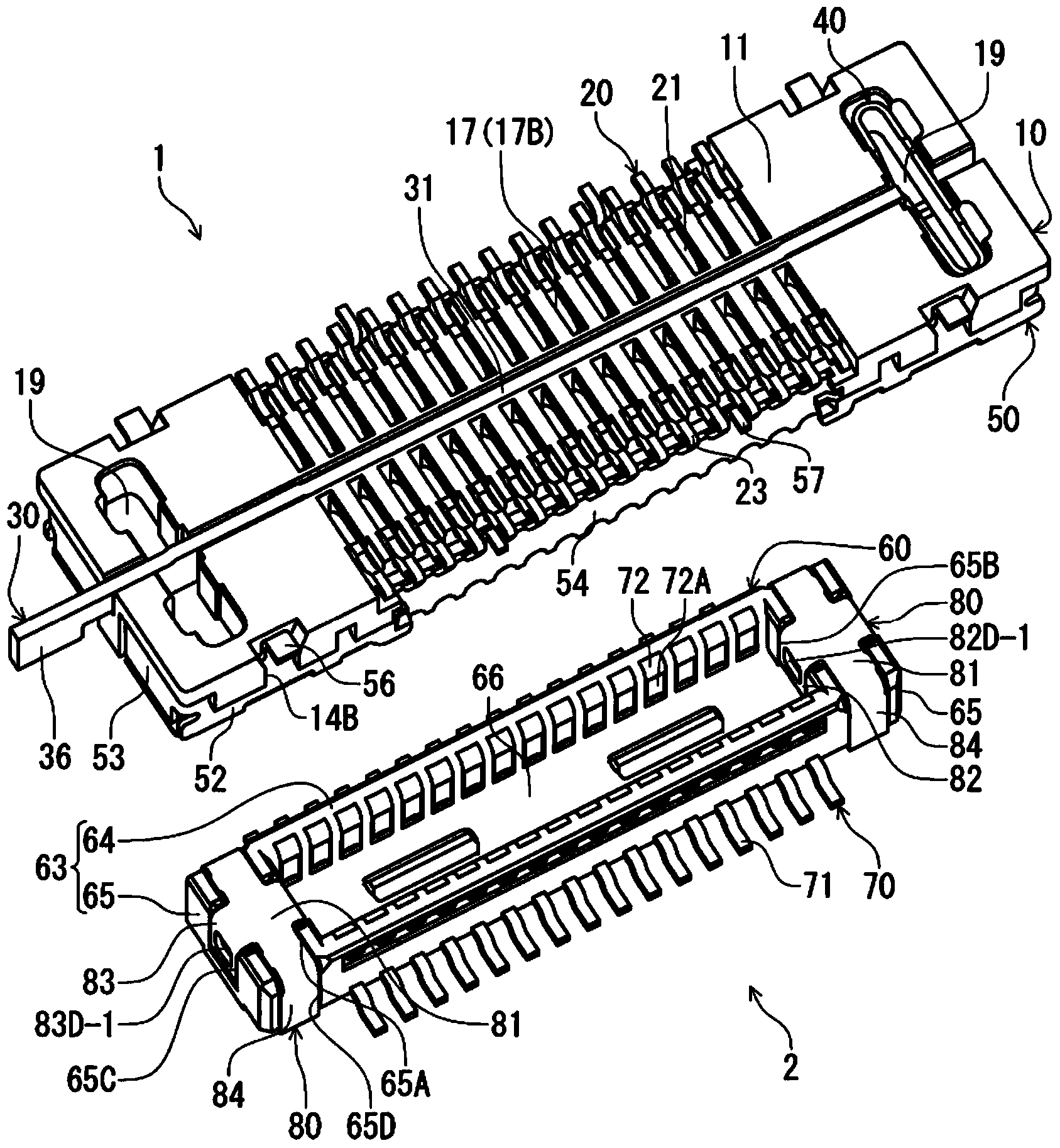
[0030] figure 1 It is a perspective view of the receptacle connector 1 according to this embodiment and the plug connector 2 fitted to the receptacle connector 1 from above, showing a state before the connectors are fitted. figure 2 will be figure 1 The perspective view in which the receptacle connector 1 and the plug connector 2 are turned upside down is shown, and is a perspective view shown in a posture where the plug connector 2 is fitted from below.

[0031] The plug connector 2 according to this embodiment and the receptacle connector 1 as a mating connector of the plug connector 2 are respectively arranged on the mounting surfaces of different circuit boards (not shown) for electrical connection to circuit boards. device, constitutes a direction at right angles with respect to the face of each circuit board ( figure 1 The up and down direction in the middle) is the connector assembly in the plugging and unplugging direction. In this embodiment, the fitting direction...

no. 2 approach >

[0097] In the first embodiment, the locked portions 82D-1, 83D-1 of the locking metal piece 80 of the plug connector 2 are provided on the edges of the hole portions 82D, 83D of the locked leg portions 82, 83, but in the second The embodiment differs from the first embodiment in that the locked portion is formed as a protrusion protruding from the plate surface of the locked leg. Figure 9 It is an enlarged cross-sectional view showing a part of the receptacle connector and the plug connector according to the second embodiment, and shows the terminals arranged on one end side of the terminal arrangement direction by using a cross section on a plane perpendicular to the width direction of the connector. The locking state of the locking metal piece of the plug connector and the matching locking metal piece of the socket connector. The shape of the plug connector 102 of the second embodiment is the same as that of the plug connector 2 of the first embodiment except for the above-...


PUM


Abstract

An electric connector with a locking metal piece is provided. Even when locking parts of a mating connector is located on any of the inner side and the outer side of the terminal wall of the electric connector in an embedded fit of the connectors, the locking parts can be locked by means of the locking metal piece. The locking metal piece (80) is formed by bending a metal plate in the plate thickness direction and comprises a base portion (81) arranged on the upper wall surface of the terminal wall (65) of a shell opposite to the mating connector, and two locked foot portions (82, 83) which extend from the base portion in the terminal arrangement direction of the shell and bend in the plate thickness direction along the terminal wall surfaces of the inner side and the outer side of the terminal wall. Locked parts which are stopped relative to the locking parts (35A, 35B) of a mating locking part (30) installed on the mating connector (1) in the connector pull-out direction are formed by hole portions, recess portions or projection portions at the two locked foot portions (82, 83).

Description

technical field [0001] The invention relates to an electrical connector, which is fitted and connected with a mating connector disposed on a mounting surface of a circuit substrate by taking the direction at right angles to the mounting surface as the direction of plugging in and out of the connector. Background technique [0002] Such an electrical connector is disclosed in Patent Document 1, for example. In this patent document 1, a receptacle connector as a mating connector is mounted on one circuit board, and a plug connector fitted and connected to the receptacle connector is mounted on the mounting surface of the other circuit board, and the two circuits are connected to each other. In a state where the mounting surfaces of the substrates are parallel, the two connectors are mated and connected with the direction perpendicular to the mounting surfaces as the fitting direction, thereby constituting an electrical connector assembly. In this patent document 1, for the re...

Claims


Application Information

Patent Timeline
Patent Type & Authority Applications(China)
IPC IPC(8): H01R13/639H01R27/00
Inventor 绿川和弥
Owner HIROSE ELECTRIC GROUP
Why Eureka
Try Eureka