
Electric drive system for new energy vehicles

An electric drive system, new energy vehicle technology, applied in control systems, AC motor control, electrical components, etc., can solve the problems of short-circuit damage to Y capacitors, inability to stop the motor, and no protection measures for Y capacitors, so as to avoid burnout , reduce destructive effects

Active Publication Date: 2017-02-15
UNITED AUTOMOTIVE ELECTRONICS SYST
View PDF6 Cites 0 Cited by
  • Summary
  • Abstract
  • Description
  • Claims
  • Application Information

AI Technical Summary

Problems solved by technology

However, the above-mentioned high-voltage electric drive system has the following faults in practical applications: When the motor is running and the motor controller is in the normal working mode, at this time one of the three phases (UVW three-phase) of the motor (U or V or W phase) suddenly Short circuit to ground, because the upper system or the motor controller cannot detect a short circuit fault of the motor relative to the ground during the operation of the motor, and cannot stop the motor, resulting in an abnormally large current flowing through the Y capacitor, causing severe heat and eventually causing the short circuit damage of the Y capacitor
[0006] To sum up, the existing high-voltage electric drive system for new energy vehicles has the following problems: 1). When the high-voltage electric drive system is working, it is impossible to diagnose a motor relative to the body or insulation failure through the upper system or the motor controller itself. Fault; 2). When a fault occurs with respect to the motor body or insulation failure, there is no effective Y capacitor protection measure, which eventually leads to short circuit damage to the Y capacitor

Method used


Image

  • Electric drive system for new energy vehicles
  • Electric drive system for new energy vehicles
  • Electric drive system for new energy vehicles

Examples


Embodiment 1

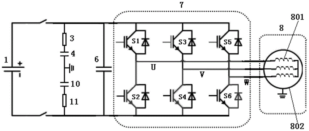
[0025] Electric drive systems for new energy vehicles, such as figure 1 As shown, it includes a high-voltage power battery 1, a DC support capacitor 6, a first Y capacitor 4, a second Y capacitor 10, a first capacitor protection device 3, a second capacitor protection device 11, a motor controller (inverter) 7, Three-phase AC motor 8;

[0026] The DC support capacitor 6 is connected in parallel at both ends of the positive pole and the negative pole of the high-voltage power battery 1;

[0027] In the motor controller 7, two input terminals are connected in parallel to both ends of the DC support capacitor 6, and three output terminals UVW are respectively connected to the three-phase input lines of the three-phase AC motor 8;

[0028] The three-phase AC motor 8, the casing 802 is directly connected to the ground of the vehicle body or indirectly connected to the ground of the vehicle body through other intermediate media;

[0029] The first Y capacitor 4 and the first capac...

Embodiment 2

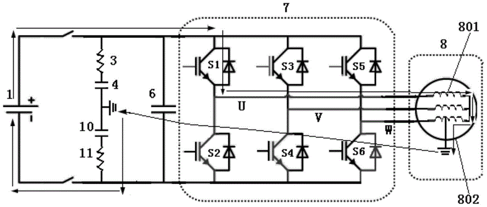
[0036] Based on the electric drive system for new energy vehicles in Embodiment 1, such as figure 2 As shown, the first capacitive protection device 3 and the second capacitive protection device 11 are resistors with variable resistance properties such as positive temperature coefficient thermistors (PTC);

[0037] For the positive temperature coefficient thermistor, when the temperature is lower than a certain value, its resistance value is small and changes little, and when the temperature rises to a certain value, its resistance value increases rapidly.

[0038]Taking the motor W-phase winding short circuit to ground as an example, when the electric drive system is in the running mode, when the W in the three-phase AC motor three-phase winding 801 is short-circuited to the three-phase AC motor casing 802 or the insulation fails, due to the upper system ( Such as the battery management system) and the motor controller 7 failed to detect the fault, so the six insulated gate ...

Embodiment 3

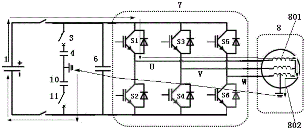
[0040] Based on the electric drive system for new energy vehicles in Embodiment 1, such as image 3 As shown, the first capacitive protection device 3 and the second capacitive protection device 11 are switching components such as a circuit breaker with an overcurrent disconnection function; the circuit breaker, when the current flowing through it is less than or equal to the set value, It is in the normally closed state; when the current flowing through it is greater than the set value, it will be automatically disconnected; the circuit breaker can be restored to the normal normally closed state through manual or electric control, and then returned to the normal normally closed state.

[0041] image 3 In the electric drive system for new energy vehicles shown, the first circuit breaker 3 is connected in series with the first Y capacitor 4 to form a group, which is connected between the positive pole of the high-voltage power battery 1 and the ground of the vehicle body; the ...


PUM


Abstract

The invention discloses an electric drive system for a new energy vehicle. The electric drive system includes a high voltage power battery, a direct current supporting capacitor, a first Y capacitor, a second Y capacitor, a motor controller, a three-phase alternating current motor, a first capacitor protection device, and a second capacitor protection device, the direct current supporting capacitor is connected with a positive electrode and a negative electrode of the high voltage power battery in parallel, two input ends of the motor controller are connected with two ends of the direct current supporting capacitor in parallel, three output ends are connected with three-phase input lines of the three-phase alternating current motor, a housing of the three-phase alternating current motor is directly in a lap joint with the vehicle body ground, the first Y capacitor and the first capacitor protection device are connected in series between the positive electrode of the high voltage power battery and the vehicle body ground, and the second Y capacitor and the second capacitor protection device are connected in series between a negative electrode of the high voltage power battery and the vehicle body ground. According to the electric drive system for the new energy vehicle in the invention, when a short circuit occurs between a winding of a phase of the motor and the housing or an insulation failure occurs, the Y capacitor in the electric drive system can be protected, and a filtering effect of the Y capacitor is not affected.

Description

technical field [0001] The invention belongs to the technical field of new energy vehicles, and in particular relates to an electric drive system for new energy vehicles. Background technique [0002] Safety capacitors are used in such occasions, that is, after the capacitor fails, it will not cause electric shock and will not endanger personal safety. [0003] According to IEC60384-14, safety capacitors are divided into two types: X capacitors and Y capacitors. X capacitors are capacitors connected across the two lines (L-N) of the power line, and metal film capacitors are generally used; Y capacitors are connected across the power lines respectively. The capacitance between the two lines and the ground (L-E, N-E) generally appears in pairs. Based on the limitation of the leakage current, the value of the Y capacitor should not be too large. Generally, the X capacitor is uF level, and the Y capacitor is nF level. The X capacitor and the Y capacitor are used in the power f...

Claims


Application Information

Patent Timeline
Patent Type & Authority Patents(China)
IPC IPC(8): H02P27/06H02H7/16H02H9/02
Inventor 徐玮卢志坚刘志明
Owner UNITED AUTOMOTIVE ELECTRONICS SYST
Learn More