
Sanding system for railway vehicle and sander thereof

A sand spreader and sand blasting technology, which is applied in the field of rail vehicles, can solve the problems of large space occupation, multiple equipment, and large changes in the amount of sanding, so as to reduce the occupied space, reduce costs, and simplify the sanding system Effect

Inactive Publication Date: 2014-10-29
ZHUZHOU ELECTRIC LOCOMOTIVE CO
View PDF5 Cites 11 Cited by
  • Summary
  • Abstract
  • Description
  • Claims
  • Application Information

AI Technical Summary

Problems solved by technology

[0003] The existing sand spreading system includes a sand box, a sand spreading device, a sand spreading nozzle, an air compressor, an air storage cylinder, and an air drying device. The compressed air generated by the air compressor is used for high-pressure sand spreading. The air pressure is not lower than 500Kpa. Therefore, an air compressor with a maximum air supply pressure of not lower than 700Kpa is required. Since the compressed air is saturated humid air, in order to prevent the humid air from condensing into water, an air storage cylinder and an air drying and purification device are required. Drying the air leads to more equipment, higher cost, and larger installation space
In addition, the sand output per unit time of the existing sand spreading system is a fixed value, usually a value in the range of 0.5kg / min to 1.5kg / min, taking 1kg / min of sand as an example, when the When running at 20m / s, the amount of sanding is 0.83g / m, and when the vehicle is running at 1m / s, the amount of sanding is 16.6g / m, the amount of sanding changes greatly, and the effect of increasing adhesion is unstable
[0004] To sum up, how to solve the problems of numerous equipment, high cost and large space occupation of the sand spreading system has become an urgent problem to be solved by those skilled in the art

Method used


Image

  • Sanding system for railway vehicle and sander thereof
  • Sanding system for railway vehicle and sander thereof
  • Sanding system for railway vehicle and sander thereof

Examples


Embodiment Construction

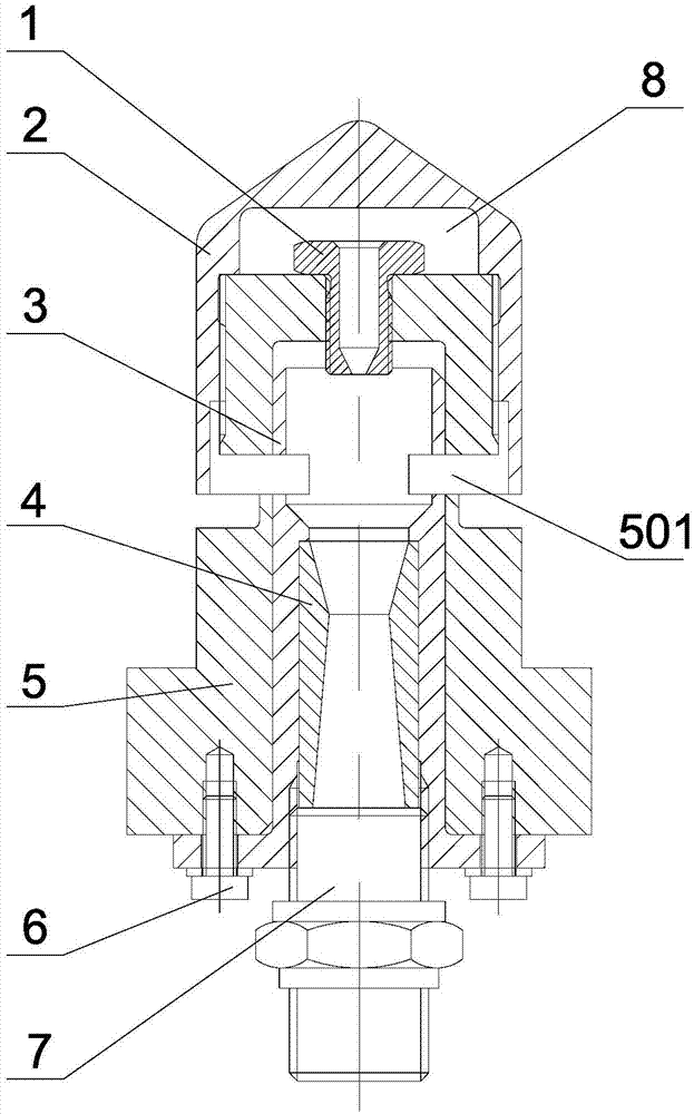
[0046] The core of the present invention is to provide a sand spreader, which adopts low-pressure sand spread, simplifies the sand spread system, lowers the cost, and reduces the space occupied by the sand spread system when installed.

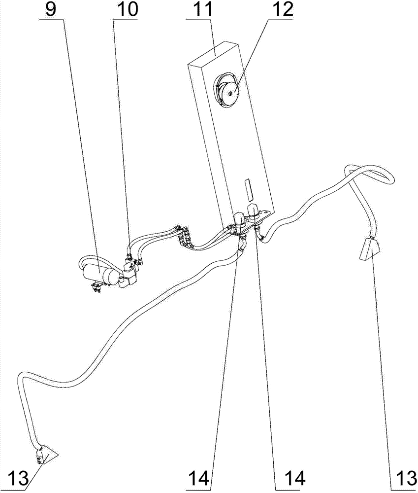
[0047] The invention also provides a sand spreading system for rail vehicles using the sand spreader, the system is simplified, the cost is reduced, and the space occupation is reduced.

[0048] The following will clearly and completely describe the technical solutions in the embodiments of the present invention with reference to the accompanying drawings in the embodiments of the present invention. Obviously, the described embodiments are only some, not all, embodiments of the present invention. Based on the embodiments of the present invention, all other embodiments obtained by persons of ordinary skill in the art without making creative efforts belong to the protection scope of the present invention.

[0049] Such as figure 1 As shown, the...


PUM


Abstract

The invention discloses a sander which comprises a sander main body, a sander cover and a sand outlet pipe, wherein the sander main body is internally provided with a sand blasting cavity provided with an opening at one end; a vent hole is formed in the inner end surface of the sand blasting cavity; the periphery of the sander main body has a sand inlet hole which is communicated with the sand blasting cavity; the sander cover is sheathed at the end of the sander main body with the vent hole, and an air chamber is formed by the sander cover and the end of the sander main body; the air chamber is communicated with compressed air; the sand outlet pipe is communicated with the sand blasting cavity in a sealing way. The sander is filled with the compressed air, negative pressure is formed in the sander relative to the atmospheric pressure in a sand box, gravel is absorbed by the negative pressure, and sanding is completed; therefore, the sanding operation can be completed by the low-pressure compressed air, and the low-pressure compressed air is not coagulated into water, so that an air storage cylinder and an air drying and purifying device are not needed, a sanding system is greatly simplified, and the space occupied by installing the system can be reduced. The invention also discloses the sanding system which applies the sander and is used for a rail train.

Description

technical field [0001] The invention relates to the technical field of rail vehicles, in particular to a sand spreader. The invention also relates to a sand spreading system for rail vehicles using the sand spreader. Background technique [0002] The function of the sand spreading system in rail vehicles is to spread sand between the wheels and the rails to increase the adhesion of the wheels and rails, which is beneficial to the traction and braking of the vehicles. [0003] The existing sand spreading system includes a sand box, a sand spreading device, a sand spreading nozzle, an air compressor, an air storage cylinder, and an air drying device. The compressed air generated by the air compressor is used for high-pressure sand spreading. The air pressure is not lower than 500Kpa. Therefore, an air compressor with a maximum air supply pressure of not lower than 700Kpa is required. Since the compressed air is saturated humid air, in order to prevent the humid air from conde...

Claims


Application Information

Patent Timeline
IPC IPC(8): B61C15/10
Inventor 段继超伍智敏程畅栋侯知青
Owner ZHUZHOU ELECTRIC LOCOMOTIVE CO
Learn More