Spindle mechanism capable of reducing vibration amplitude

A vibration amplitude and spindle technology, which is applied in the direction of thin material handling, conveying filamentous materials, transportation and packaging, etc., can solve the problems of increasing the difficulty of spindle installation and reducing the vibration amplitude of reel spindles, etc.

Inactive Publication Date: 2014-10-29
ZHEJIANG NORMAL UNIVERSITY +1
View PDF8 Cites 7 Cited by
  • Summary
  • Abstract
  • Description
  • Claims
  • Application Information

AI Technical Summary

Problems solved by technology

However, the self-fixing core structure of the spindle frame of the above-mentioned textile machinery needs to install the spindle between the two spind

Method used


Image

  • Spindle mechanism capable of reducing vibration amplitude
  • Spindle mechanism capable of reducing vibration amplitude
  • Spindle mechanism capable of reducing vibration amplitude

Examples


Embodiment Construction

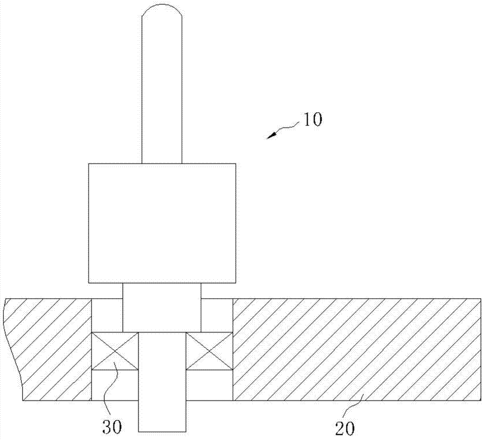
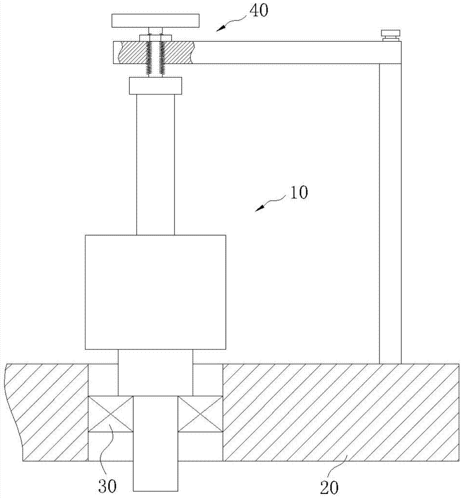
[0022] like Figure 1~2 As shown, a spindle mechanism that can reduce the vibration amplitude includes a spindle 10 and a spindle base 20. The spindle 10 is installed on the spindle base 20 through a bearing 30, and also includes a centering device 40 installed on the spindle base 20.

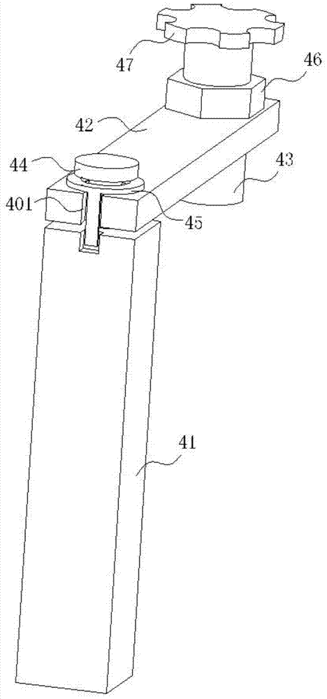
[0023] like image 3 , Figure 5 , Image 6 As shown, the centering device 40 includes a pillar 41 installed on the spindle base 20 , a connecting rod 42 movably connected to the pillar 41 through an adjusting screw 44 , and a fastening member 43 threaded on the end of the connecting rod 42 that can be raised and lowered. The connecting rod 42 can rotate around the central axis of the pillar 41 , and the fastening component 43 is located above the spindle 10 . A nut 46 is installed on the fastening member 43 , and the nut 46 is located above the connecting rod 42 . A handle 47 is mounted on the top of the fastening component 43 .

[0024] Among them, such as image 3 , Figure 4 As shown...


PUM


Abstract

The invention discloses a spindle mechanism capable of reducing vibration amplitude. The spindle mechanism capable of reducing vibration amplitude comprises a spindle (10), a spindle base (20), a bearing (30) and a core fixing device (40) installed on the spindle base (20), wherein the core fixing device (40) comprises a fastening component (43) located above the spindle (10), a groove (431) is formed in the bottom end of the fastening component (43), the groove (431) can cover the top end of the spindle (10), and therefore when the spindle rotates, the vibration amplitude of the spindle is limited by the groove. According to the technical scheme, the core fixing device is additionally arranged on the spindle, the original structure of the spindle does not need to be changed, installation is convenient, broken yarn caused by large vibration amplitude when the spindle rotates can be avoided, and winding smoothness is improved.

Description

Technical field: [0001] The invention relates to the field of textile machinery design, in particular to a spindle mechanism capable of reducing vibration amplitude. Background technique: [0002] At present, due to the irregular structure of the reel and spindle in the winding process of the textile machine, the weight of the spinning machine continues to increase during the winding process, causing its vibration to intensify, affecting the tightness of the yarn winding, and easily causing yarn breakage, which affects the production progress. [0003] In view of the above technical problems, the invention with the authorized announcement number CN 202785079U and the authorized announcement date of March 13, 2013 discloses a self-fixing core structure for textile machine spindle racks. The device includes a U-shaped bracket, and the two ends of the U-shaped bracket correspond to A spindle frame is provided, wherein at least one spindle frame is movably connected with a U-sha...

Claims


Application Information

Patent Timeline
IPC IPC(8): B65H54/54
Inventor 顾子安
Owner ZHEJIANG NORMAL UNIVERSITY
Why Eureka
Try Eureka