Calibration method for installation error angles between dual-shaft rotation inertial navigation system's rotating shafts and sensitive shafts

A technology of installation error angle and dual-axis rotation, which is applied in the field of inertial navigation calibration, can solve the problems that the gyro sensitive axis and the outer ring rotation axis do not coincide, affect the system attitude accuracy, and cannot strictly guarantee the coincidence of the gyro sensitivity axis and the rotation axis, etc.

Active Publication Date: 2014-10-29
BEIJING AUTOMATION CONTROL EQUIP INST
View PDF2 Cites 17 Cited by
  • Summary
  • Abstract
  • Description
  • Claims
  • Application Information

AI Technical Summary

Problems solved by technology

[0004] For the actual engineering product of the dual-axis rotation system, due to the processing and installation accuracy of the inner and outer ring shafts, the two rotation axes may not be perpendicular; The existence of a fixed zero error angle on the disk will also cause the gyro sensitive axis and the rotating axis to misalign. For example, the zero error of the inner ring axis code disk will cause the gyro sensitive axis in the inner ring rotation plane to misalign with the outer ring rotating axis after the demodulation of the inner ring.
Since the sensitive axis of the gyro does not coincide with the rotating axis, demodulation error will be caused during demodulation, and the error will fluctuate with the rotation of the rotating mechanism, and the fluctuation value can reach more than angular minutes, which seriously affects the attitude accuracy of the system

Method used


Image

  • Calibration method for installation error angles between dual-shaft rotation inertial navigation system's rotating shafts and sensitive shafts
  • Calibration method for installation error angles between dual-shaft rotation inertial navigation system's rotating shafts and sensitive shafts
  • Calibration method for installation error angles between dual-shaft rotation inertial navigation system's rotating shafts and sensitive shafts

Examples


Embodiment Construction

[0030] The present invention is described in detail below in conjunction with specific embodiment:

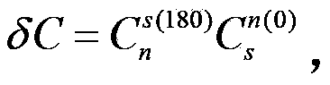
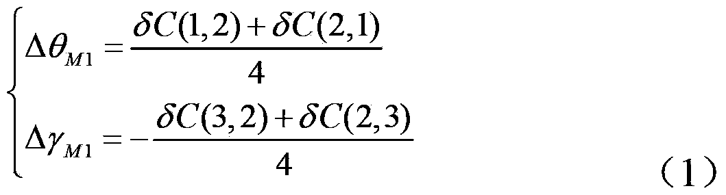
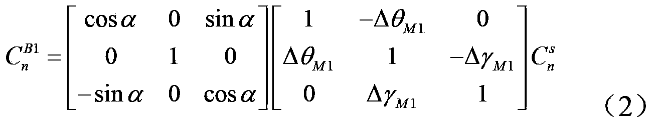
[0031] The invention proposes a method for calibrating the installation error angle between the rotating shaft and the sensitive shaft of the dual-axis rotary inertial navigation system. Through the calibrating method, it is possible to calibrate the inside and outside of the two rotating shafts inside and outside the dual-axis rotary inertial navigation system and the sensitive shaft. Two installation error angles, after the calibration is completed, the attitude demodulation error caused by the installation error angle is eliminated, and the attitude accuracy of the system is improved.

[0032] There are two types of inner and outer rings in the dual-axis rotary inertial navigation system. One is that the inner ring axis is the yaw axis, and the other is that the outer ring axis is the yaw axis. To facilitate the description of the method, one is assumed here: assuming that t...


PUM


Abstract

Belonging to inertial navigation calibration methods, the invention in particular relates to a calibration method for installation error angles between a dual-shaft rotation inertial navigation system's rotating shafts and sensitive shafts. According to the method, four installation error angles delta theta M1, delta gamma M1, delta psi M2, and delta gamma M2 are calibrated, and then compensation is conducted to complete demodulation work of dual-shaft rotation inertial navigation. The specific steps include: 1. calibration and compensation of the inner ring error angles delta theta M1 and delta gamma M1; and 2. calibration and compensation of the inner ring error angles delta psi M2 and delta gamma M2. With the invention, by calibration of the installation error angles between the dual-shaft rotation inertial navigation system's rotating shafts and sensitive shafts, navigation attitude demodulation error caused by the installation error angles can be eliminated, and the navigation attitude precision of the system is improved.

Description

technical field [0001] The invention belongs to an inertial navigation calibration method, in particular to a calibration method for an installation error angle between a rotating shaft and a sensitive shaft of a dual-axis rotary inertial navigation system. Background technique [0002] The rotary modulation technology is an automatic compensation technology for the inertial device error of the inertial navigation system, which can significantly improve the system navigation accuracy on the basis of the existing inertial device level. The rotary inertial navigation system often uses the rotary mechanism to drive the optical strapdown inertial unit (IMU) to continuously rotate or index, modulate the zero offset of the inertial device perpendicular to the rotation axis, and use the code disc on the rotary mechanism to measure the rotation angle. The attitude of the IMU body coordinate system is demodulated in real time, so as to obtain the attitude in the demodulated vehicle c...

Claims


Application Information

Patent Timeline
Patent Type & Authority Applications(China)
IPC IPC(8): G01C25/00
CPCG01C25/005
Inventor 周章华刘冲吴亮华练涛李群姜述明
Owner BEIJING AUTOMATION CONTROL EQUIP INST
Why Eureka
Try Eureka