Attitude determination method and device

A technique for determining a method and an attitude, which is applied in the field of attitude determination methods and devices, and can solve problems such as low attitude accuracy

Pending Publication Date: 2021-03-05
BEIJING HORIZON ROBOTICS TECH RES & DEV CO LTD
View PDF0 Cites 4 Cited by
  • Summary
  • Abstract
  • Description
  • Claims
  • Application Information

AI Technical Summary

Problems solved by technology

However, the position of the target object with the same pose relative to the optical axis of the camera is different, and the imaging in the image is also different, which leads to the low pose accuracy of the target object determined directly by using the region of interest.

Method used


Image

  • Attitude determination method and device
  • Attitude determination method and device
  • Attitude determination method and device

Examples


Embodiment Construction

[0037] Hereinafter, exemplary embodiments according to the present disclosure will be described in detail with reference to the accompanying drawings. Apparently, the described embodiments are only some of the embodiments of the present disclosure, rather than all the embodiments of the present disclosure, and it should be understood that the present disclosure is not limited by the exemplary embodiments described here.

[0038] Application overview

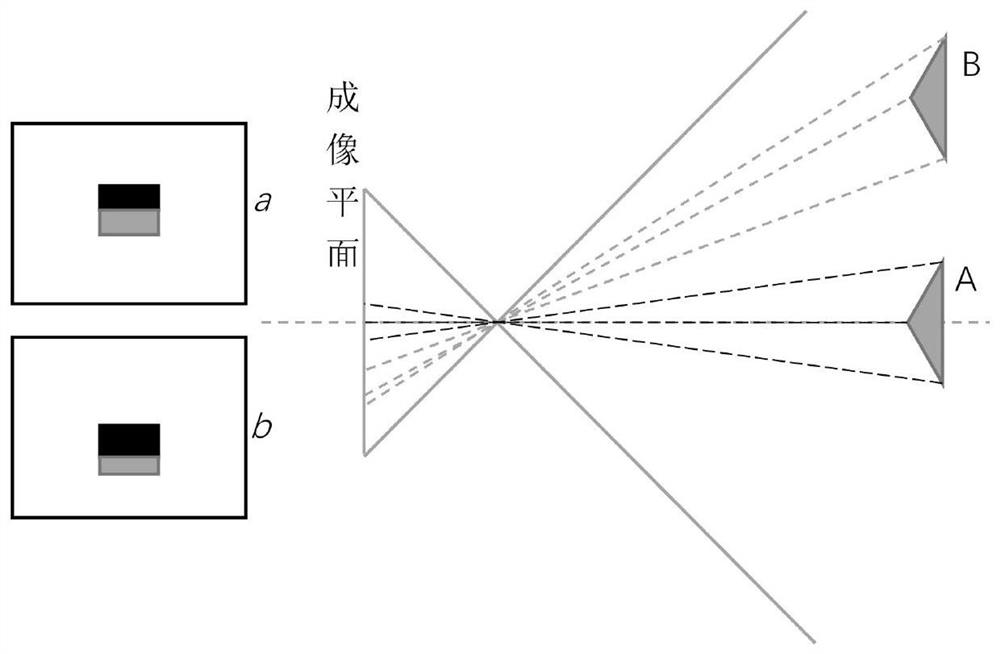
[0039] Such as figure 1 As shown, taking the triangular prism in the image as the target object, when the triangular prism is at position A (optical axis position), the obtained image is a, that is, two rectangles with the same height and width at the top and bottom; when the triangular prism is translated to position B (The attitude of the triangular prism does not change), and the obtained image is b, that is, two rectangles with different heights and widths. It can be seen that even if the attitude of the target object is t...


PUM


Abstract

The invention discloses an attitude determination method, a device, a computer readable storage medium and electronic equipment. The method comprises the steps of obtaining an initial pixel coordinateof a target object in an image; determining an attitude angle between the target object and an optical axis of the camera according to the initial pixel coordinates and internal parameters of the camera; obtaining corrected pixel coordinates corresponding to the target object according to the initial pixel coordinates, the attitude angle and the camera internal parameters; and determining the attitude of the target object according to the corrected pixel coordinates, a preset model and the attitude angle. According to the method, the initial pixel coordinates are corrected by utilizing the attitude angle between the target object and the optical axis of the camera, the corrected pixel coordinates are obtained, and the attitude of the target object is obtained according to the corrected pixel coordinates, so that the determined attitude of the target object is relatively high in accuracy.

Description

technical field [0001] The present disclosure relates to the technical field of image processing, and more particularly, relates to a pose determination method and device. Background technique [0002] Estimating the pose of the target object is to determine the orientation of the target object, which has a wide range of applications in the fields of robot vision and motion tracking. [0003] At present, when using images to estimate the pose of a target object, the selected region of interest is often directly input into a pre-trained model to determine the pose of the target object. However, the position of the target object with the same posture relative to the camera optical axis is different, and the imaging in the image is also different, which leads to a low pose accuracy of the target object determined directly by using the region of interest. Contents of the invention [0004] In order to solve the above technical problems, the present disclosure is proposed. Emb...

Claims


Application Information

Patent Timeline
Patent Type & Authority Applications(China)
IPC IPC(8): G06T7/70G06K9/32
CPCG06T7/70G06V10/25
Inventor 储刘火
Owner BEIJING HORIZON ROBOTICS TECH RES & DEV CO LTD
Why Eureka
Try Eureka