6R industrial robot inverse kinematics solving method

An industrial robot and inverse kinematics technology, applied in manipulators, manufacturing tools, program-controlled manipulators, etc., can solve problems such as complicated results, great influence on convergence and precision, and complicated solution process, so as to improve efficiency and attitude accuracy Effect

Active Publication Date: 2020-08-07
TIANJIN UNIV
View PDF7 Cites 4 Cited by
  • Summary
  • Abstract
  • Description
  • Claims
  • Application Information

AI Technical Summary

Problems solved by technology

[0003] At present, the commonly used robot kinematics methods are mainly analytical method and numerical method. Analytical method, such as matrix method, needs to establish a corresponding coordinate system on each joint, establish a forward kinematics model by coordinate transformation, and solve it in inverse kinematics. In general, the inverse transformation matrix method is usually used, the solution process is complicated, the result is relatively cumbersome, and the efficiency is relatively low
The numerical solution method directly solves the constraint equations, and the real number solution of any mechanism can be obtained through iterative operations, but usually not all solutions can be obtained. Generally speaking, the selection of the initial value and the search algorithm have a great influence on the convergence and precision
The geometric inverse solution method has been studied by some scholars, and it has certain limitations for certain structures.

Method used


Image

  • 6R industrial robot inverse kinematics solving method
  • 6R industrial robot inverse kinematics solving method
  • 6R industrial robot inverse kinematics solving method

Examples


Embodiment Construction

[0051] In order to further understand the invention content, characteristics and effects of the present invention, the following embodiments are enumerated hereby, and detailed descriptions are as follows in conjunction with the accompanying drawings:

[0052] See Figure 1 to Figure 7 , a 6R industrial robot inverse kinematics solution method, the method includes the following steps:

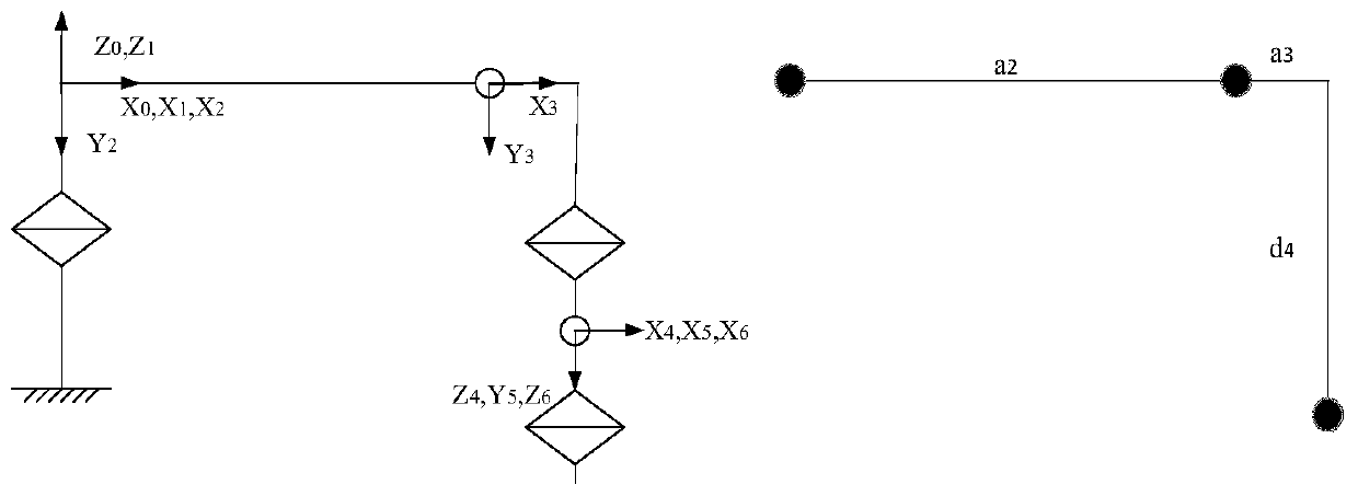
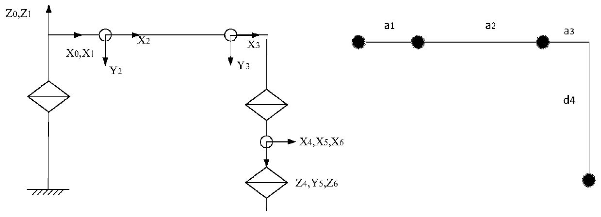
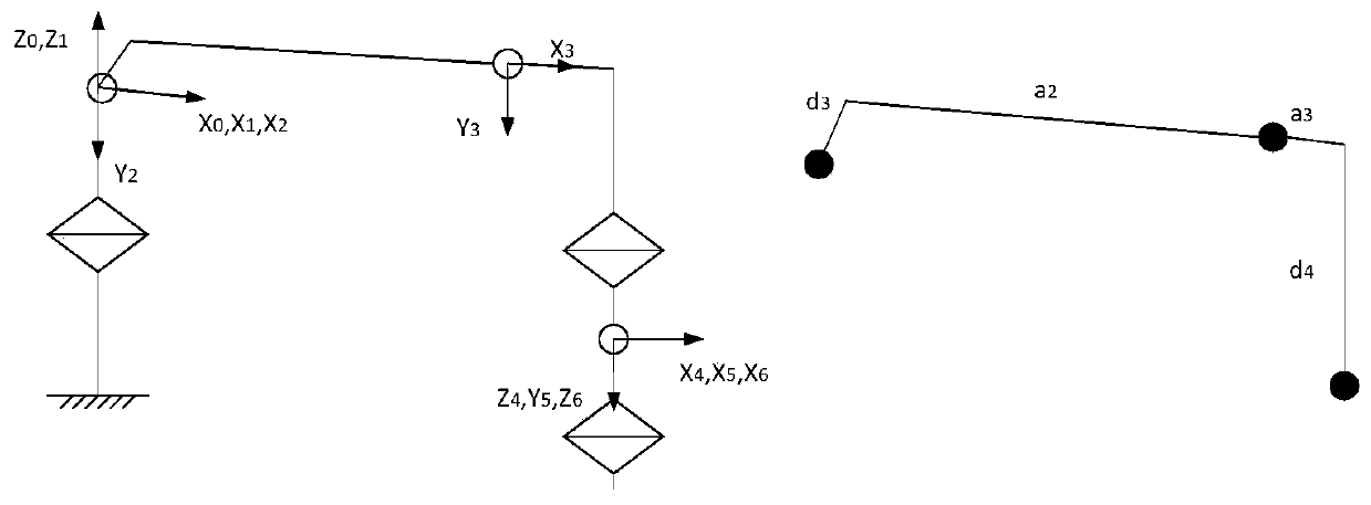
[0053] Step 1: Establish the coordinate system, geometric simplified model and D-H table of the 6R robot;

[0054] Step 2: According to the geometrically simplified model, establish the functional relationship between the joint angle of the first joint and the spatial coordinate of the origin of the coordinate system of the end link;

[0055] Step 3: Under the condition that the joint angle of the first joint has been determined, the spatial position relationship of the second link and the third link is simplified into a triangle, and the functional relationship between the joint angle of the ...


PUM


Abstract

The invention discloses a 6R industrial robot inverse kinematics solving method. The method comprises the following steps that a 6R robot geometric simplification model and a D-H table are established; according to the geometric simplification model, a function relational expression between a joint angle of a first joint and spatial coordinates of the origin of a tail end connecting rod coordinatesystem are established; under the condition that the joint angle of the first joint is determined, the spatial position relation of a second connecting rod and a third connecting rod is simplified into a triangle, and a function relational expression of joint angles of the second joint and the third joint is established; under the condition that the joint angles of the first joint, the second joint, the third joint and the fourth joint are determined, z-axis direction vectors of a fourth connecting rod coordinate system, a fifth connecting rod coordinate system and a sixth connecting rod coordinate system are used for establishing a space geometric model with the joint axis of the fifth joint as the center axis, and a joint angle function relational expression of the fifth joint is established firstly through the space geometric model; and then a function relational expression of the joint angles of the fourth joint and the sixth joint is established. According to the 6R industrial robot inverse kinematics solving method, the efficiency and attitude precision of the robot inverse solution method are improved.

Description

technical field [0001] The invention relates to the field of inverse kinematics of industrial robots, in particular to a method for solving the inverse kinematics of 6R industrial robots. Background technique [0002] At present, industrial robot kinematics is one of the important research directions of robotics. It has a great influence on robot control, robot dynamics and trajectory planning, and is the basis for studying robot dynamics and trajectory planning. It describes and studies machines from a geometric or mechanical perspective. Human motion characteristics, regardless of the force or moment that causes these motions, are divided into forward kinematics and inverse kinematics. Forward kinematics is to find the position and attitude of the end effector of the robot relative to the reference coordinate system for a given robot with known geometric parameters of the connecting rod and joint variables. Inverse kinematics is to solve the robot joint variables that ca...

Claims


Application Information

Patent Timeline
Patent Type & Authority Applications(China)
IPC IPC(8): B25J9/16G06F30/20
CPCB25J9/16G06F30/20B25J9/1664
Inventor 王太勇李书伟张晓超徐明达
Owner TIANJIN UNIV
Why Eureka
Try Eureka