A capacity optimization design method of upfc converter

A design method and converter technology, applied in the direction of instruments, calculations, AC network circuits, etc., can solve problems such as complex calculation process

Active Publication Date: 2018-12-07
XJ ELECTRIC +3
View PDF2 Cites 0 Cited by
  • Summary
  • Abstract
  • Description
  • Claims
  • Application Information

AI Technical Summary

Problems solved by technology

[0004] The purpose of the present invention is to provide an intuitive and simple method for designing the capacity of UPFC series-side converters and a method for designing the capacity of parallel-side converters, which are used to solve the problem of complex calculation process in the prior art

Method used


Image

  • A capacity optimization design method of upfc converter
  • A capacity optimization design method of upfc converter
  • A capacity optimization design method of upfc converter

Examples


Embodiment Construction

[0038] UPFC converter capacity design, including series side converter capacity design and parallel side converter capacity design.

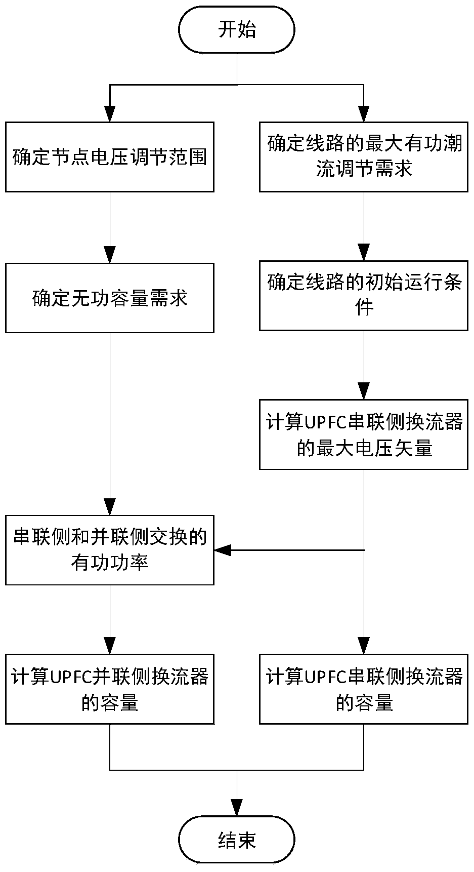
[0039] Such as figure 2 As shown, the UPFC series side converter capacity design method provided by the present invention comprises the following steps:

[0040] a. According to the boundary conditions of the power grid and load growth forecast and other factors, determine the maximum adjustment demand of line power flow;

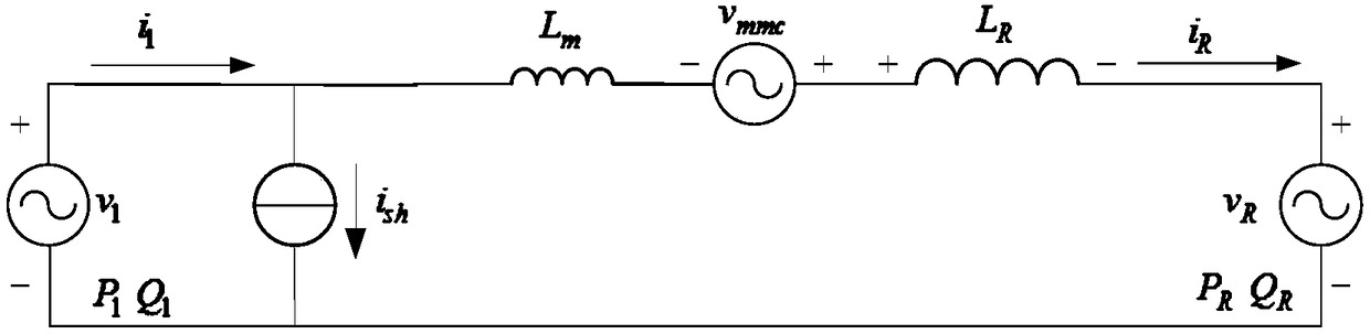
[0041] b. According to the constraint conditions of the maximum transmission capacity of the active power flow of the line, combined with the maximum adjustment demand of the line power flow, determine the initial active power flow of the line when the UPFC performs the maximum power flow regulation of the line, that is, P 0 =P max -ΔP max ;

[0042] c. According to the leakage reactance and line impedance of the transformer, calculate the voltage vector to be output by the UPFC series side converter, specifically: As ...


PUM


Abstract

The invention relates to a UPFC current converter capacity optimization design method, and the method comprises the steps: firstly determining the maximum adjustment demands of the flow of a UPFC line according to the boundary conditions of a power grid and load increase prediction; secondly determining the initial active flow of line transmission according to the transmission constraint condition of the active flow of the line, and calculating the voltage vector to be outputted by a UPFC series-side current converter through combining the impact of the leakage reactance of a transformer; and finally obtaining the capacity of the UPFC series-side current converter according to the maximum active flow of the line. Moreover, the capacity of a parallel-side current converter is calculated according to the active power exchanged by the series-side and parallel-side current converters and the reactive capacity of the parallel-side current converter when a UPFC adjusts the active flow of the line. The method starts from the boundary conditions of a power grid, obtains the capacity of the UPFC current converter according to the maximum transmission power of the line and the maximum flow adjustment demands of the UPFC, and is simple and convenient for calculation.

Description

technical field [0001] The invention relates to a method for designing the capacity of a UPFC series-side converter, and belongs to the field of flexible power transmission in power systems. Background technique [0002] The unified power flow controller (UPFC) is a series-parallel hybrid FACTS device based on voltage source converters, which can quickly, flexibly and continuously adjust the power flow of the line and improve the uneven distribution of power flow in the transmission section. Improving the utilization efficiency of transmission lines can also inject reactive power into the grid, stabilize system node voltages, and improve power supply reliability. [0003] Aiming at the design problem of the capacity of the UPFC series-side converter, it is necessary to use PSASP to conduct power flow analysis and calculation, and to draw the characteristic curve of the ability of UPFC to control the power change of the grid year by year, and find out the control critical poi...

Claims


Application Information

Patent Timeline
Patent Type & Authority Patents(China)
IPC IPC(8): H02J3/00G06F17/50
CPCG06F30/00G06F2111/04H02J3/00H02J2203/20Y02E60/00
Inventor 姚为正冯宇鹏吴金龙何青连刘欣和李道洋王先为杨美娟
Owner XJ ELECTRIC
Why Eureka
Try Eureka