Touch identification method and system for infrared touch screen
A technology of infrared touch screen and identification method, which is applied in the input/output process of data processing, instruments, electrical and digital data processing, etc., can solve the problems of long processing time and slow response speed, improve the recognition speed and reduce the processing area. effect of reducing the number of light paths
- Summary
- Abstract
- Description
- Claims
- Application Information
AI Technical Summary
Problems solved by technology
Method used
Image
Examples
Embodiment 1
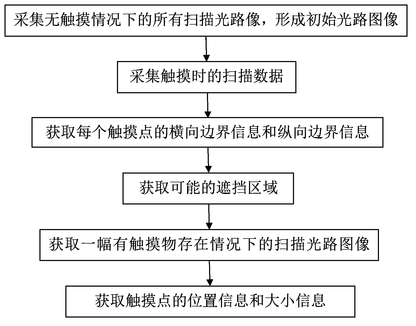
[0062] A kind of identification method that is used for infrared touch screen of this embodiment, its flow chart is as follows figure 1 As shown, the specific implementation includes the following steps:
[0063] S1: Collect all scanning light paths under no-touch conditions to form an initial light path image. Specific steps are as follows:
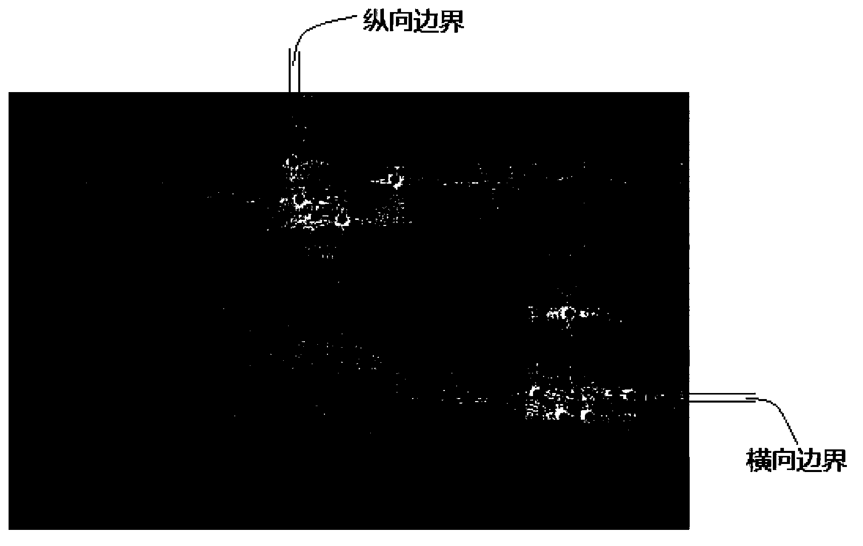
[0064] S11: Generate a background image with a preset ratio to the size of the touch screen, and the color of the background image is a single color. Such as figure 2 As shown, the color of the background image is set to black.
[0065] The size of the touch screen and the size of the background image can be in any ratio, which is set by the user according to the specific application environment. In this embodiment, the preset ratio is 1:1, so that the coordinates of the optical path on the touch screen and the corresponding coordinates of the light path in the background image do not need to be converted.
[0066] As another imple...
Embodiment 2
[0085] In this embodiment, different from the above-mentioned embodiment 1, in step S6 of this embodiment, for each of the acquired possible occlusion areas, each of the possible occlusion areas from the initial optical path image The scanning optical path that is blocked within is processed, and the other scanning optical paths are not processed. Specifically, the steps for acquiring a scanning optical path image in the presence of a touching object are as follows:
[0086] S521. For each of the obtained possible occlusion areas, traverse each pixel, and count the number of light paths passing through each pixel, and the light paths passing through each pixel include a blocked light path and an unblocked light path; this implementation In this example, a linear rasterization algorithm is used to determine which pixels the scanning light path passes through in the possible occlusion area.
[0087] S522. For each pixel, subtract the number of blocked light paths passing through...
Embodiment 3
[0090] In this embodiment, on the basis of the above-mentioned embodiments, the step S4 further includes the step of aggregating the possible occlusion areas, and the specific method is:
[0091] When a shading optical path passes through at least the two longitudinal shading areas at the same time, for each of the longitudinal shading areas, compare the distance between the longitudinal shading area and the other longitudinal shading areas that the same shading optical path passes through, if the vertical shading The distance of the area is less than the preset vertical threshold, then aggregated into the same vertical occlusion area;
[0092] When a shading optical path passes through at least the two lateral shading areas at the same time, for each of the lateral shading areas, compare the distance between the lateral shading area and the other lateral shading areas that the same shading optical path passes through, if the lateral shading If the distance of the regions is s...
PUM
 Abstract
Description
Claims
Application Information
 - R&D
- Intellectual Property
- Life Sciences
- Materials
- Tech Scout
- Unparalleled Data Quality
- Higher Quality Content
- 60% Fewer Hallucinations
Browse by: Latest US Patents, China's latest patents, Technical Efficacy Thesaurus, Application Domain, Technology Topic, Popular Technical Reports.
© 2025 PatSnap. All rights reserved.Legal|Privacy policy|Modern Slavery Act Transparency Statement|Sitemap|About US| Contact US: help@patsnap.com


