Bunched cable connecting socket, bunched cable connecting plug and bunched cable testing fixture

A technology for bundling cables and connecting sockets, which is applied in the direction of two-part connection device, parts of the connection device, connection, etc., can solve the problems of easy twisting, low efficiency, high labor intensity, etc.

Active Publication Date: 2014-10-29
深圳市众恒世讯科技股份有限公司
View PDF6 Cites 2 Cited by
  • Summary
  • Abstract
  • Description
  • Claims
  • Application Information

AI Technical Summary

Problems solved by technology

It can be seen that the entire loading process of the test is done manually, and the manual twisting structure is not only inefficient, but also easy to twist and hurt, labor-intensive and has problems of poor reliability, so it is not convenient for industrial standard operation

Method used


Image

  • Bunched cable connecting socket, bunched cable connecting plug and bunched cable testing fixture
  • Bunched cable connecting socket, bunched cable connecting plug and bunched cable testing fixture
  • Bunched cable connecting socket, bunched cable connecting plug and bunched cable testing fixture

Examples


Embodiment 1

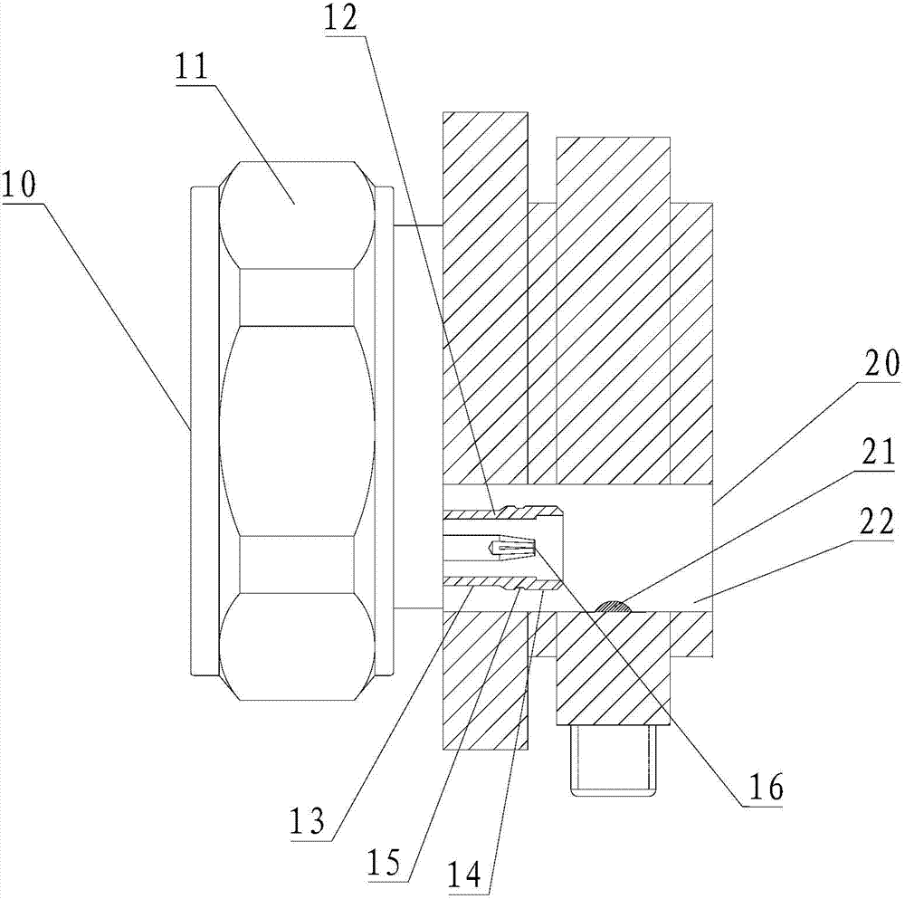
[0022] One end of the main body is provided with a first socket 10 , and a locking nut 11 is provided on the outside of the main body corresponding to the first socket 10 , so that the first socket 10 of the main body can be locked on the required equipment through the locking nut 11 . Correspondingly, the other end of the main body is provided with a plurality of second sockets 20 , and the main body is provided with a connecting structure corresponding to each second socket 20 . That is, the socket of the present invention can be designed as a one-to-many connection mode, that is, the first socket 10 is the main port, so it occupies a large area and is usually arranged in the middle of the main body, while the second socket 20 is each external detection port. Therefore, more are distributed on the other surface of the main body. In order to ensure convenient connection, each second socket 20 is provided with the above-mentioned connection structure, so that the multi-line acc...

Embodiment 2

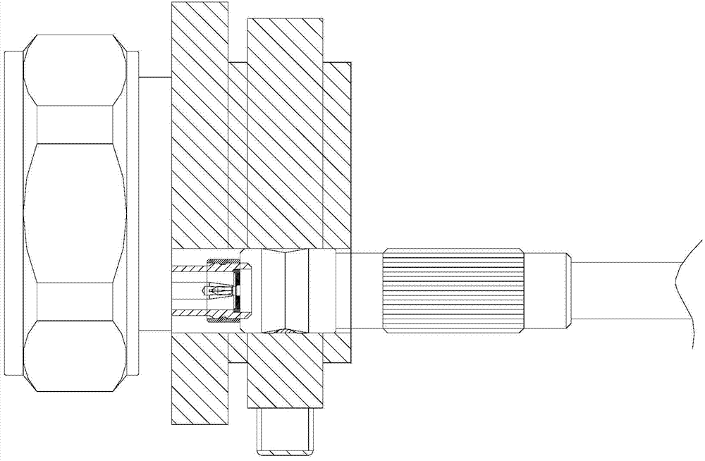
[0024] Such as Figure 4 , 5 As shown, in this embodiment, the main body is mainly composed of two parts, the main seat 1 and the auxiliary seat 2 . Wherein, one end of the main seat 1 is provided with a first socket 10, and the other end is provided with a flange 17, and the sub-seat 12 in the connection structure (the structure with multiple sub-seats 12 as shown in the figure) is arranged at the other end of the main seat. Lan 17 on. Corresponding to the main seat, a flange 23 is provided at one end of the auxiliary seat 2, and a second socket 20 and a guide hole 22 for the connection structure are provided at the other end. Further, the main seat 1 and the auxiliary seat 2 are attached to each other through respective flanges 17, 23 and connected by means such as bolts.

[0025] The biggest benefit of splitting the socket main body into two parts by adopting the scheme of this embodiment is to simplify the production process of the socket with complex structure. The gu...

Embodiment 3

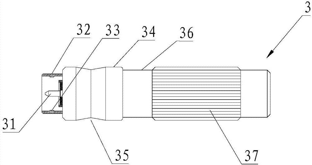
[0027] The outer surface of the connecting section of the sub-seat 12 is plane.

[0028] In this embodiment, the outer surface of the sub-seat 12 is a plane, which means that it is not a threaded surface of a conventional common connector, so that it can support the axial entry and exit of the plug, and facilitate the realization of the quick plug-in and pull-out function.


PUM


Abstract

The invention provides a bunched cable connecting socket, a bunched cable connecting plug and a bunched cable testing fixture. The bunched cable connecting socket comprises a columnar body which is provided with a connecting structure corresponding to a second spigot, the connecting structure comprises a guide hole and a subsidiary socket, the sidewall of the guide hole is provided with a first boss / groove, and the outer wall of a connecting section in a connecting wall of the subsidiary socket is provided with a second groove / boss. The bunched cable connecting plug comprises a guide section, the sidewall of the guide section is provided with a third groove / boss, and the inner wall of a socketing section at the end of the guide section is provided with a fourth boss / groove. The plug can be plugged into and unplugged out of the socket blindly quickly by the aid of guide effect of the guide hole in the socket on the plug. Further, two sets of fastening structures correspondingly formed by the connecting section of the connecting wall of the subsidiary socket of the socket and the inner wall of the socketing section of the plug as well as the guide hole of the socket and the sidewall of the guide section of the plug can be in fastened match, so that more tight-fitting fixed connection between the socket and the plug is guaranteed, testing data stability is guaranteed and testing efficiency is improved.

Description

technical field [0001] The invention relates to a communication equipment connector, in particular to a bundled cable connection socket, a plug and a bundled cable test tool. Background technique [0002] Some parts of existing communication base stations (such as common bundled cable assemblies) need to be tested by testing equipment before assembly to ensure the stable operation of the entire communication system. In the existing test equipment, the method used in the test is to manually tighten the two ends of the test part first, then connect the test head to the test instrument to form a path, and then loosen and remove the part from the test head after the test is completed. . It can be seen that the entire loading process of the test is done manually, and the manual screwing structure is not only inefficient, but also easy to twist and hurt, labor-intensive and has problems of poor reliability, so it is not convenient for industrial standard operation. Contents of ...

Claims


Application Information

Patent Timeline
Patent Type & Authority Applications(China)
IPC IPC(8): H01R13/631H01R13/639H01R31/06H01R24/00G01R1/04
Inventor 段小文凌杨
Owner 深圳市众恒世讯科技股份有限公司
Why Eureka
Try Eureka