Jumper cap combination

A technology of jumping caps and caps, which is applied in the direction of coupling devices, electrical components, circuits, etc., and can solve problems such as inconvenient operation

Inactive Publication Date: 2014-10-29
HONG FU JIN PRECISION IND (SHENZHEN) CO LTD +1
View PDF0 Cites 1 Cited by
  • Summary
  • Abstract
  • Description
  • Claims
  • Application Information

AI Technical Summary

Problems solved by technology

The jumper cap is small in size, and the jumper cap needs to be removed and inserted frequently to change the position of the jumper cap, which is inconvenient to operate

Method used


Image

  • Jumper cap combination
  • Jumper cap combination
  • Jumper cap combination

Examples


Embodiment Construction

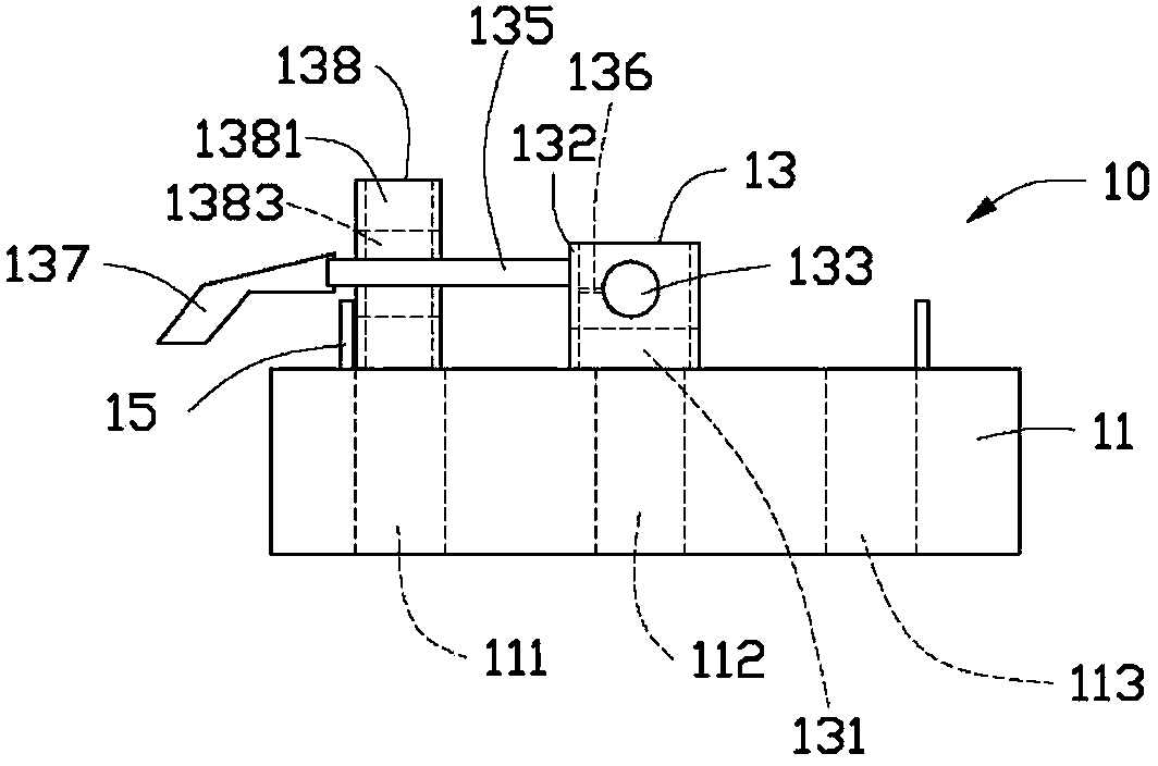
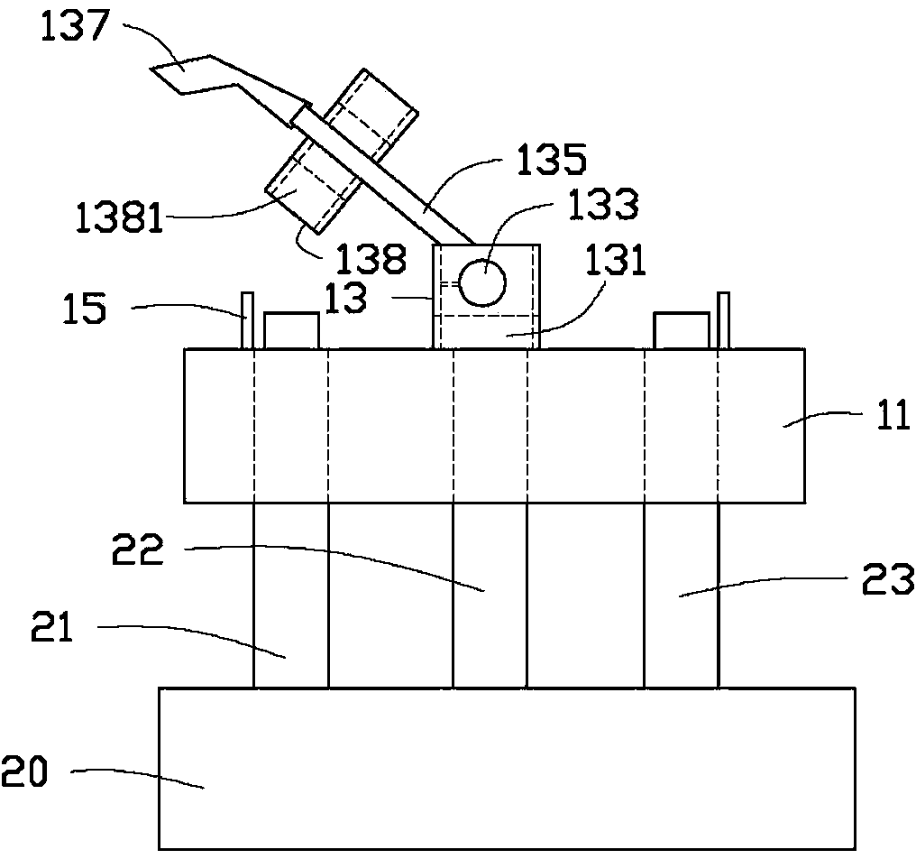
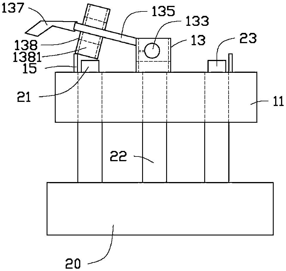
[0012] Please refer to figure 1 with figure 2 A preferred embodiment of the jumper assembly of the present invention includes a jumper 10 and first pins 21 , second pins 22 and third pins 23 disposed on the circuit board 20 .

[0013] The jump cap 10 includes a body 11 . The body 11 defines a first through slot 111 , a second through slot 112 and a third through slot 113 . The top surface of the main body 11 is provided with a pivot block 13 directly above the second through slot 112 . A groove 131 is defined at the bottom of the pivoting block 13 . The pivoting block 13 is provided with a conductive piece 132 protruding into the groove 131 . The pivot block 13 has a rotating shaft 133 . A pivot rod 135 is rotatably connected to the rotating shaft 133 . The rotating shaft 133 and the pivoting rod 135 are made of conductive material. The rotating shaft 133 is electrically connected to the conductive sheet 132 through a wire 136 . An insulated handle 137 is provided at ...


PUM


Abstract

A jumper cap combination contains a jumper cap, a first pin, a second pin and a third pin. The jumper cap contains a body which is provided with a first through groove, a second through groove and a third through groove. The first pin, the second pin and the third pin are respectively contained in the first through groove, the second through groove and the third through groove. A conductive pivoting rod which is electrically connected with the second pin is pivoted at the second pin on the top surface of the body, and the pivoting rod can rotate to be electrically connected with the first pin or the third pin. According to the jumper cap, the second pin can be controlled to communicate with or not to communicate with another pin by rotating the pivoting rod. The jumper cap is convenient to operate.

Description

technical field [0001] The invention relates to a jump cap combination. Background technique [0002] Jumper caps are usually used on computer motherboards to connect specific two pins. The jumper cap is small in size, and the jumper cap needs to be removed and inserted frequently to change the position of the jumper cap, which is inconvenient to operate. Contents of the invention [0003] In view of the above, it is necessary to provide a jumper combination for convenient operation of the jumper. [0004] A jumper cap combination, including a jumper cap, a first stitch, a second stitch and a third stitch, the jumper cap includes a body, the body is provided with a first slot, a second slot and a third slot Slot, the first pin, the second pin and the third pin are accommodated in the first through slot, the second through slot and the third through slot respectively, and the top surface of the body is pivoted at the second pin with a conductive An electrically connected...

Claims


Application Information

Patent Timeline
IPC IPC(8): H01R31/08H01R4/26H01R35/04
Inventor 王冠
Owner HONG FU JIN PRECISION IND (SHENZHEN) CO LTD
Why Eureka
Try Eureka