Liquid crystal display

A liquid crystal display and display area technology, applied in static indicators, instruments, etc., can solve the problem that the effective display area of ​​liquid crystal display cannot be reached, and achieve the effect of improving the effect of narrow borders

Inactive Publication Date: 2014-11-05
AU OPTRONICS CORP
View PDF0 Cites 40 Cited by
  • Summary
  • Abstract
  • Description
  • Claims
  • Application Information

AI Technical Summary

Problems solved by technology

For liquid crystal display applications of automotive products (such as center consoles, instrument panels, etc.), they often require th

Method used


Image

  • Liquid crystal display
  • Liquid crystal display
  • Liquid crystal display

Examples


Embodiment Construction

[0030] In order to make the technical content disclosed in this application more detailed and complete, reference may be made to the drawings and the following various specific embodiments of the present invention, and the same symbols in the drawings represent the same or similar components. However, those skilled in the art should understand that the examples provided below are not intended to limit the scope of the present invention. In addition, the drawings are only for schematic illustration and are not drawn according to their original scale.

[0031] The specific implementation manners of various aspects of the present invention will be further described in detail below with reference to the accompanying drawings.

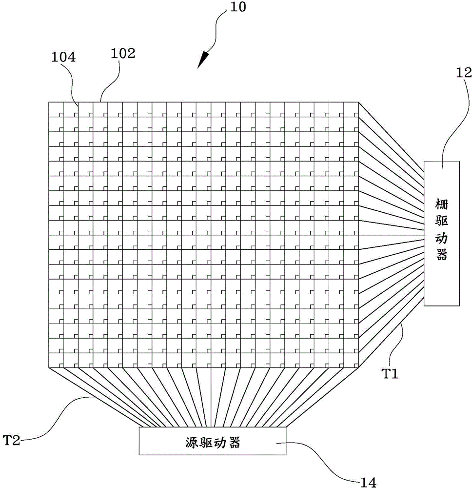
[0032] figure 1 A schematic diagram showing an arrangement of effective display areas of a liquid crystal display in the prior art. refer to figure 1 , a conventional liquid crystal display usually includes a display panel. The active area 10 of the dis...


PUM


Abstract

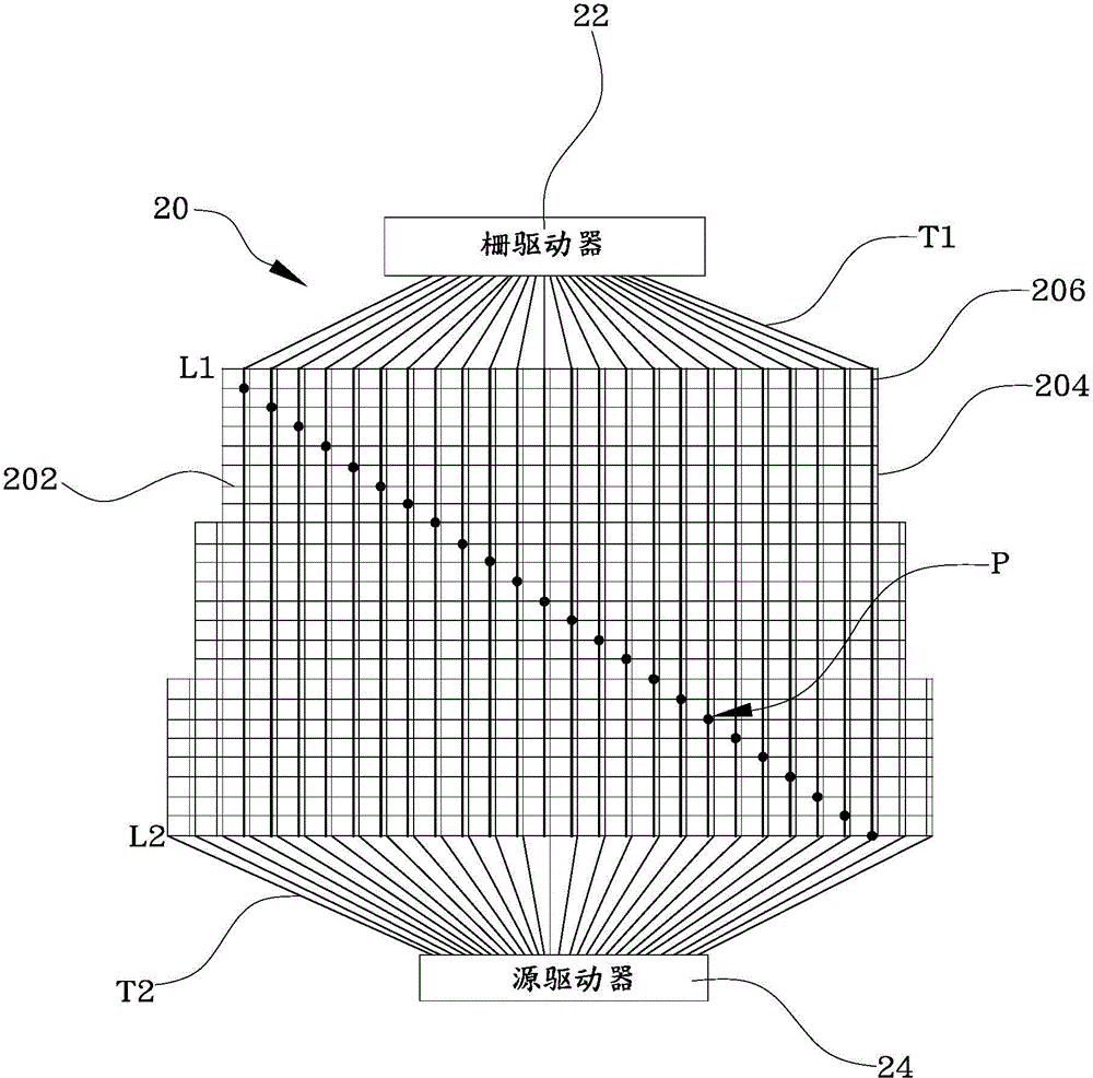
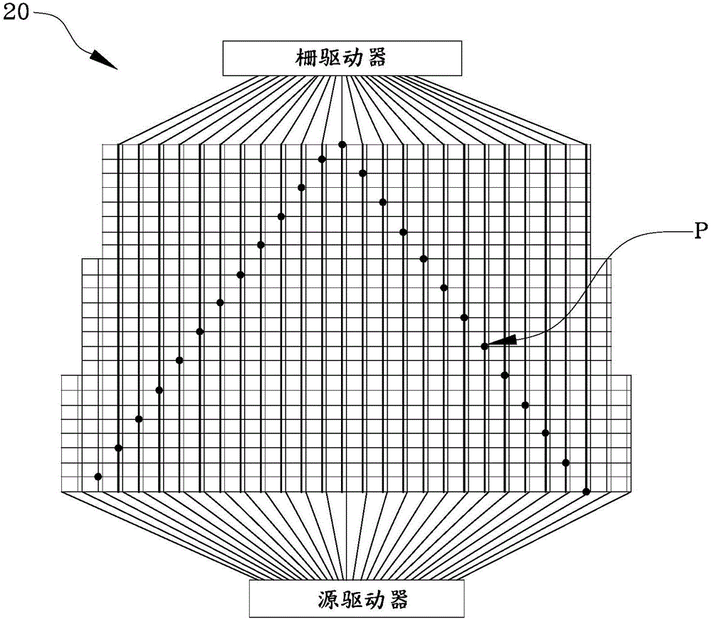
The invention provides a liquid crystal display. The liquid crystal display comprises an effective display region, a gate driver and a source driver, wherein the effective display region comprises a plurality of gate lines, source lines and signal transfer lines arranged in a staggered mode, the gate lines are vertical to the source lines, and the signal transfer lines are vertical to the gate lines; the gate driver comprises a plurality of first terminals respectively electrically connected with the corresponding signal transfer lines; the source driver comprises a plurality of second terminals respectively electrically connected with the corresponding source lines; the gate driver and the source driver are respectively arranged at two parallel sides of the ladder-shaped effective display region; and the gate lines and the corresponding signal transfer lines are electrically conducted via a transfer pad to enable the gate lines to receive gate drive signals of the gate driver. Compared with the prior art, the gate driver and the source driver are arranged at two parallel sides, signal wiring does not need to occupy space at the left side and the right side of the panel, and effects of a narrow border can be further enhanced.

Description

technical field [0001] The invention relates to the technical field of liquid crystal display, in particular to a liquid crystal display based on an arrangement structure of effective display areas. Background technique [0002] In the prior art, a liquid crystal display usually includes a display panel, which has a plurality of data lines (data lines), a plurality of gate lines (or called scanning lines) interlaced with these data lines, and liquid crystals arranged in a matrix. Box (LC cell). In addition, a thin film transistor (Thin Film Transistor, TFT) is also included at the intersection of the data line and the gate line, wherein the gate of the TFT is electrically connected to the gate line, and the source of the TFT is electrically connected to the data line. And the drain of the TFT is electrically connected to the pixel electrode. In addition, the display panel also configures a gate driver to sequentially provide gate driving signals to the gate lines, and a so...

Claims


Application Information

Patent Timeline
IPC IPC(8): G09G3/36G02F1/133
Inventor 周政盈
Owner AU OPTRONICS CORP
Why Eureka
Try Eureka