Pushbutton switch

A switch and cover technology, applied in the field of push switches, can solve the problems of increased manufacturing cost, large frictional resistance, and unsmooth pressing touch, etc., and achieve the effect of simplifying the structure, reducing frictional resistance, and reducing operating noise

Inactive Publication Date: 2014-11-05
EXCEL CELL ELECTRONICS
View PDF4 Cites 8 Cited by
  • Summary
  • Abstract
  • Description
  • Claims
  • Application Information

AI Technical Summary

Problems solved by technology

[0005] Although the push switch 1 can complete the function of turning on and off the power supply by pressing the action, in order to smoothly rotate the contact piece 13, in addition to the rotary seat 14, the piston 16, and the button must be arranged between the housing 12 and the base 11 17 and the spring 15 and other elements that can be interlocked with each other, but also on the housing 12, the button 17 and the piston 16, structures such as guiding protrusions, guiding slopes, guiding grooves and ratchets that cooperate with each other will be formed respectively. Not only the number of required components is large, but also the corresponding relationship between the matching dimensions, slopes, and configuration positions of each structure must be considered, and the structure is more complicated and the manufacturing cost is easily increased.
[0006] When the piston 16 is rotated relative to the housing 12, the second guide inclined surface 163 simultaneously contacts the first guide inclined surface 123 to slide, forming a larger contact area and greater friction between the two. Resistance, easy to form a less smooth pressing touch
In addition, when the piston 16 rotates relative to the housing 12 until the limiting protrusions 162 are respectively aligned with the next guide groove 124, the elastic restoring force of the spring 15 will drive the protrusion 162 to move along the guide groove 124 quickly. upward firing, so that the second guide slope 163 hits the limit end surface 125 formed on the top of the guide groove 124 respectively, causing the switch 1 to easily emit a relatively large impact sound when it is operated.

Method used


Image

  • Pushbutton switch
  • Pushbutton switch
  • Pushbutton switch

Examples


Embodiment Construction

[0035] The present invention will be described in detail below in conjunction with the accompanying drawings and embodiments.

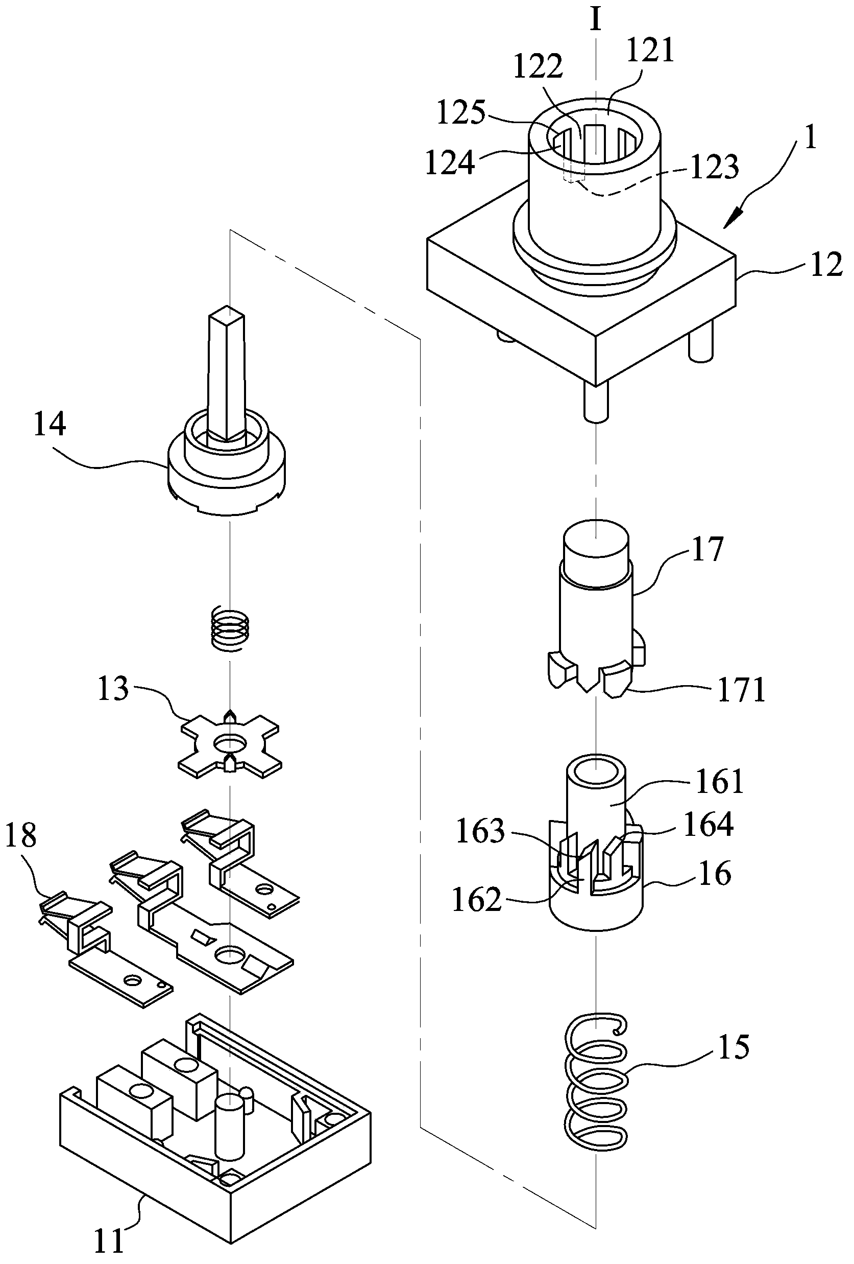
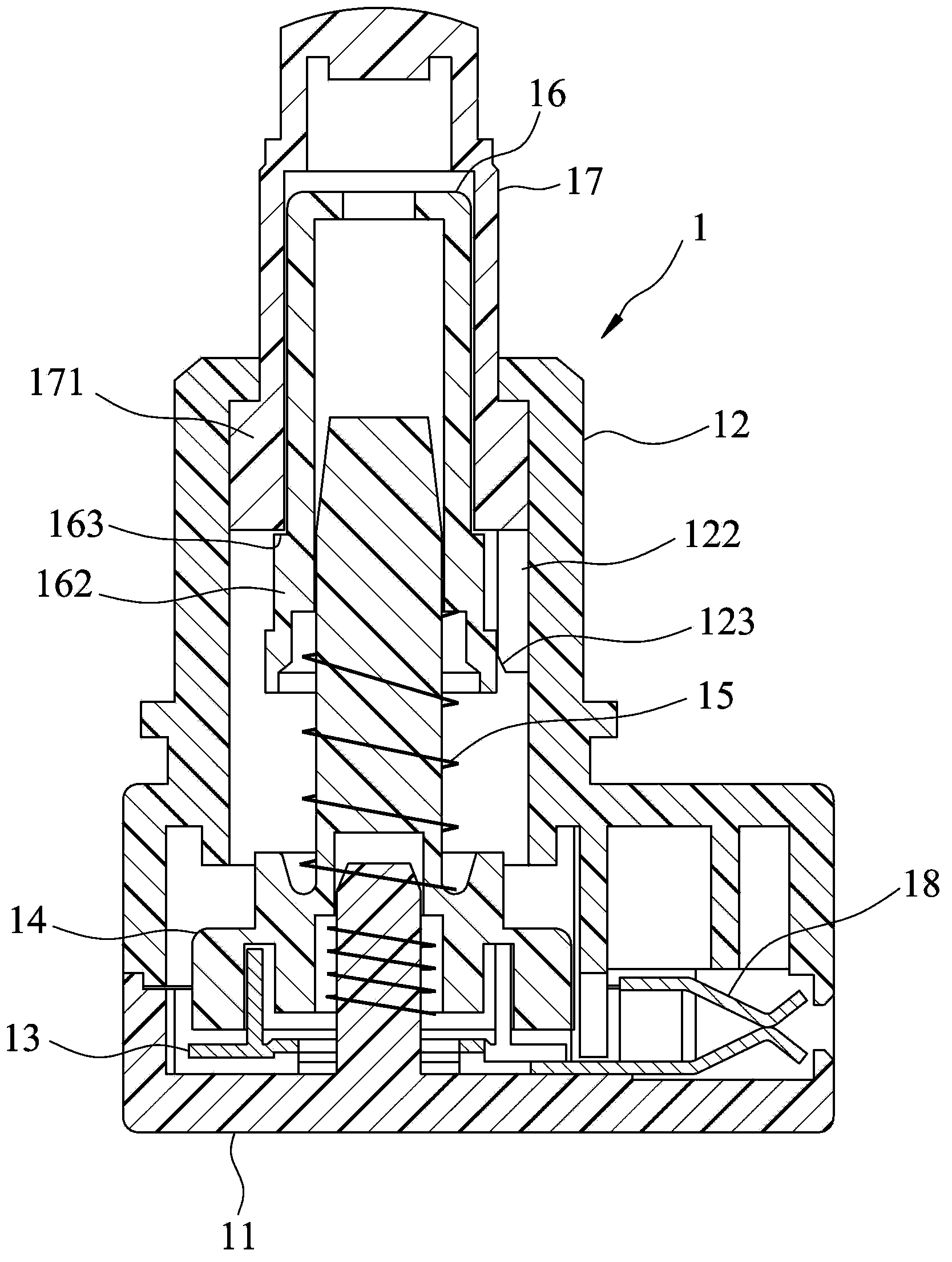
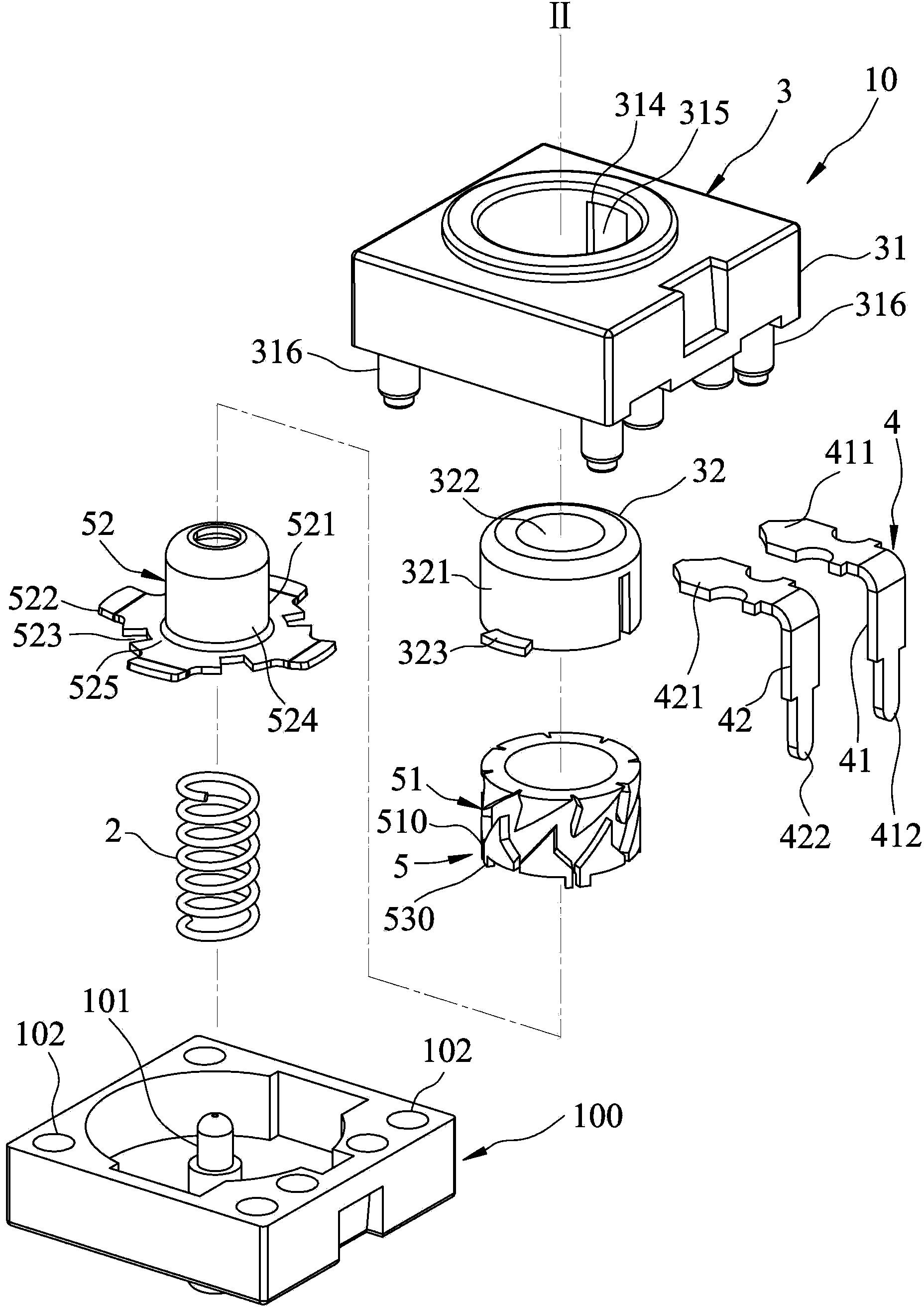
[0036] refer to image 3 , Figure 4 and Figure 6 , a preferred embodiment of the push switch 10 of the present invention is suitable for being installed on a base 100, and includes an elastic element 2 arranged on the base 100, and a cover unit 3 correspondingly engaged with the base 100 , an electrical connection unit 4 positioned between the cover unit 3 and the base 100 , and a movable mechanism 5 installed between the elastic element 2 and the cover unit 3 .

[0037] The elastic element 2 is arranged on the base 100 along an axis II. In this embodiment, the elastic element 2 is a spring, and the base 100 is an independent element designed to be correspondingly combined with the housing unit 3, and has an upward protrusion along the axis II for the The elastic element 2 is sleeved and positioned on the pillar 101 , and a plurality of installa...


PUM


Abstract

A pushbutton switch includes a shell body, a resilient member, and a movable unit movable relative to the shell body between an upper limit position and a lower limit position. The movable unit includes a drive member and an electrical contact member driven by the drive member to move between a plurality of contact positions and a plurality of non-contact positions. The drive member has a plurality of inclined rod-engaging surfaces. When the movable unit is moved from the upper limit position to the lower limit position, one of the rod-engaging surfaces moves on a guide rod of the shell body, thereby resulting in rotation of the drive member relative to the shell body so as to covert the electrical contact member between the contact positions and the non-contact positions.

Description

technical field [0001] The invention relates to a press switch, in particular to a press switch with simplified structure and reduced press noise. Background technique [0002] refer to figure 1 and figure 2 , an existing push switch 1 has a base 11 correspondingly engaged, a housing 12, a rotatable contact piece 13 installed between the base 11 and the housing 12, and a rotatable contact piece 13 for the contact piece 13 to engage. The rotating base 14, a spring 15 sleeved on the rotating base 14, a piston 16 pushed against the spring 15 and sleeved on the rotating base 14, a button 17 sleeved on the piston 16, and many A conductive sheet 18 corresponding to the contact sheet 13 is positioned on the base 11 at intervals. [0003] The housing 12 has an inner wall surface 121 formed around an axis I, a plurality of guide protrusions 122 extending longitudinally downward along the inner wall surface 121 at intervals and respectively terminating at a first guide inclined su...

Claims


Application Information

Patent Timeline
Patent Type & Authority Applications(China)
IPC IPC(8): H01H13/14H01H3/12
CPCH01H13/58H01H13/52H01H13/585
Inventor 李尉慈
Owner EXCEL CELL ELECTRONICS
Why Eureka
Try Eureka