
Balance valve having function of improving actuating sensitivity

A balance valve and sensitivity technology, applied in the field of balance valves, can solve the problems of reduced sensitivity, excessive friction coefficient, loss of mobility and balance water temperature function, etc., to achieve the effect of improving sensitivity and automatically removing scale

Active Publication Date: 2015-03-11
童炳荣
View PDF4 Cites 0 Cited by
  • Summary
  • Abstract
  • Description
  • Claims
  • Application Information

AI Technical Summary

Problems solved by technology

[0006] 1. Since the movable spool of the known balance valve and the fixed valve tube are in the shape of a long straight wall contact and fit, the friction coefficient of the movable spool is still too large when it is displaced and actuated, causing its sensitivity to decrease. regret
[0007] 2. Because the balance valve is immersed in water for a long time, scale will gradually form on the wall of the fixed valve tube and the movable valve core after using for a period of time according to the quality of the pipeline water. The preset fit gap between the spool and the fixed valve tube is quite small, so when the scale is generated, the gap between the movable spool and the fixed valve tube will be filled by the scale and become a tight fit state, thereby causing the movable valve The movement of the core is not smooth, or even completely loses its mobility and the function of balancing water temperature.

Method used


Image

  • Balance valve having function of improving actuating sensitivity
  • Balance valve having function of improving actuating sensitivity
  • Balance valve having function of improving actuating sensitivity

Examples


Embodiment Construction

[0037] The following will clearly and completely describe the technical solutions in the embodiments of the present invention with reference to the accompanying drawings in the embodiments of the present invention. Obviously, the described embodiments are only some, not all, embodiments of the present invention. Based on the embodiments of the present invention, all other embodiments obtained by persons of ordinary skill in the art without creative efforts fall within the protection scope of the present invention.

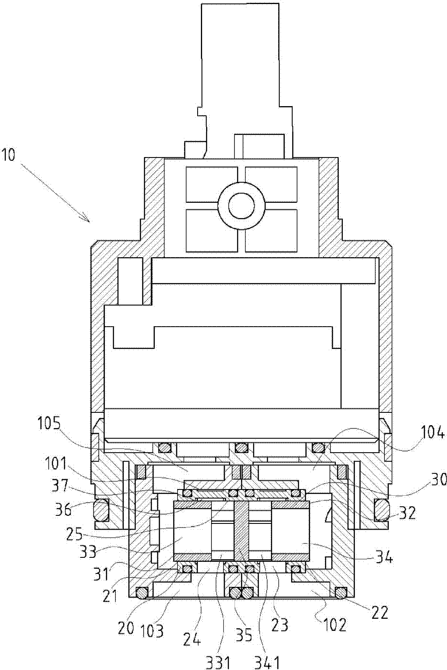
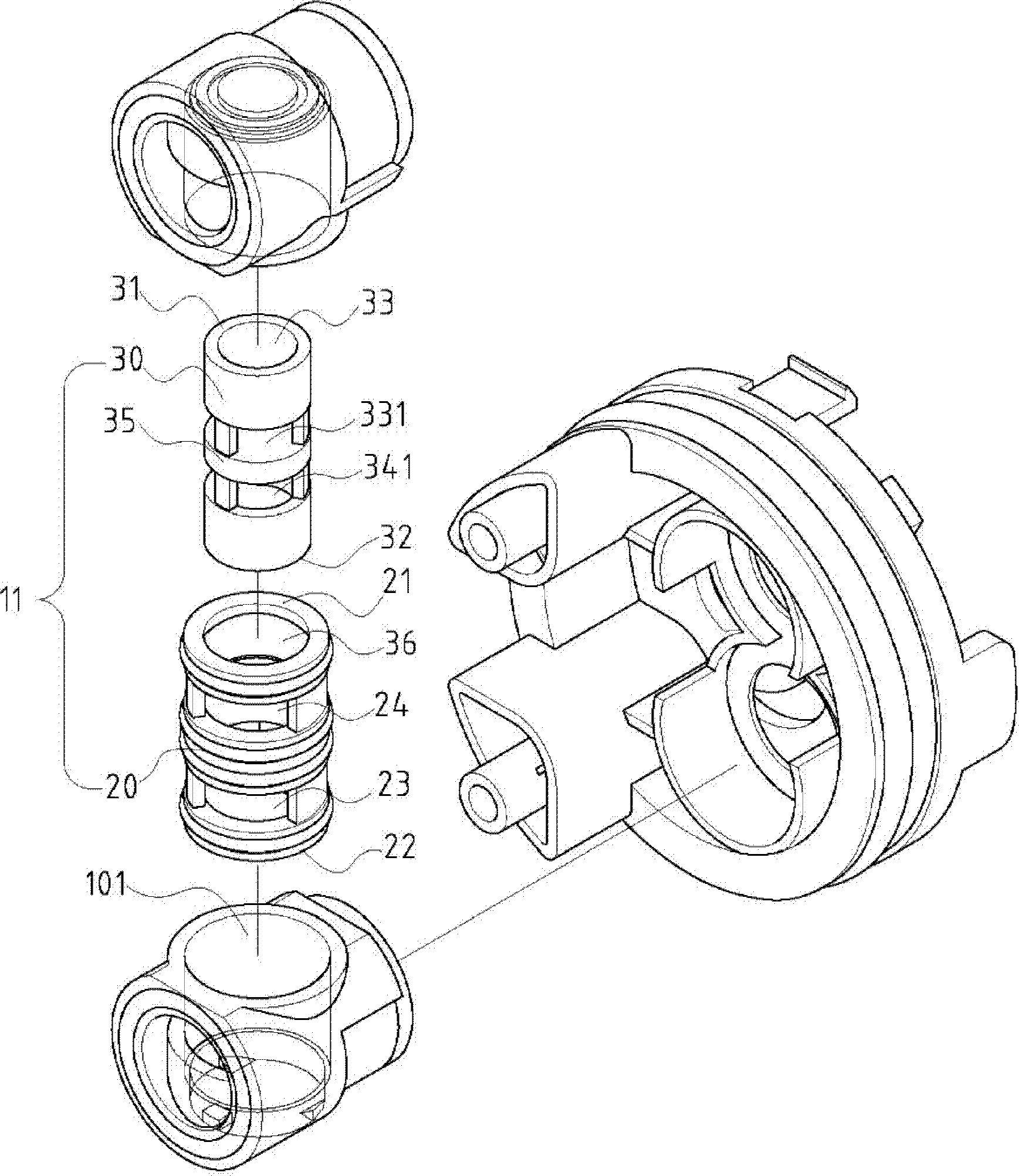
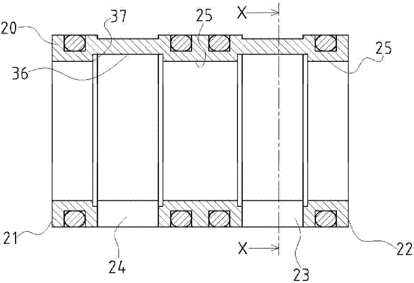
[0038] Please refer to Figures 1, 2, and 3, which are preferred embodiments of the balance valve with the function of improving the actuation sensitivity of the present invention. These embodiments are for illustration purposes only, and are not subject to the structure of these embodiments in the patent application. limits.

[0039] Please refer to Figures 1 to 6, which are preferred embodiments of the balance valve structure of the present invention with the func...


PUM


Abstract

The invention provides a balance valve having a function of improving the actuating sensitivity. The balance valve is accommodated in an accommodating space formed for a dual-temperature ceramic valve, and comprises a fixed valve tube and a movable valve core, wherein the fixed valve tube comprises a first port, a second port and cold and hot water through holes; an inner tube wall is formed inside the fixed valve tube; the movable valve core is assembled in the inner tube wall of the fixed valve tube, and is kept in a transverse reciprocating moving state; the two ends of the movable valve core are depressed inwards, so that a hot water through groove and a cold water through groove are formed; and the hot water through groove and the cold water through groove are isolated from each other by using a clapboard. The technical characteristics are that: inner grooves in the form of inwardly-concave surfaces are formed at positions, which correspond to the cold and hot water through holes, on the inner tube wall of the fixed valve tube, the set widths of the inner grooves are equal to or larger than those of the cold and hot water through holes, and the contact friction area between the movable valve core and the inner tube wall of the fixed valve tube can be reduced through the inner grooves, so that the actuating sensitivity of the movable valve core is improved, and the balance valve has the practical advances of scraping of water scales, prolonging of the service life, and the like.

Description

technical field [0001] The invention relates to a cold and hot water balance valve, in particular to a balance valve with the function of improving actuation sensitivity. Background technique [0002] In view of the problems that the traditional dual-temperature ceramic valve is prone to overheating and scalding due to the accidental turning of the faucet by hand during use, and the instability of hot and cold water pressure makes it difficult to control the water temperature. The interior of the ceramic valve is combined with an improved structural type of a hot and cold water balance valve (referred to as a balance valve in the present invention). [0003] Although there are quite a lot of ceramic valve products with balancing valves and related technology patents on the market, overall, there are still some problems and shortcomings in the existing ceramic valve products with balancing valves. Improve overcoming. [0004] Generally, the structure of the conventional bal...

Claims


Application Information

Patent Timeline
Patent Type & Authority Patents(China)
IPC IPC(8): F16K27/00
Inventor 童炳荣
Owner 童炳荣
Learn More