
A push-card assembly structure for a horizontal relay

A technology of assembling structure and pushing card, applied in relays, electromagnetic relays, detailed information of electromagnetic relays, etc., can solve the problems of too much plastic dander, too frequent contact matching, long contact matching time, etc., to achieve reliable support effect and reduce contact Fit opportunity and contact fit time, and the effect of reducing the contact friction area

Active Publication Date: 2022-07-29
SICHUAN HONGFA ELECTROACOUSTIC
View PDF0 Cites 0 Cited by
  • Summary
  • Abstract
  • Description
  • Claims
  • Application Information

AI Technical Summary

Problems solved by technology

However, due to the interference fit structure between the push rod of the push card and the moving spring socket of the moving reed, no matter in the assembly process of the push card and the moving reed or in the service process of the horizontal magnetic circuit relay, There will still be more plastic flakes
[0006] The generated plastic flakes are mainly concentrated in the matching space between the moving reed and the static reed, and the fitting space between the moving reed and the static reed is very sensitive to the presence of plastic flakes. Accumulation will reduce the service stability of the horizontal magnetic circuit relay and affect the service life
[0007] After repeated observation and careful research, the reason why the above two structural forms produce more plastic lint in the matching space between the moving reed and the static reed is that the push rod of the push card and the moving spring insert of the moving reed The contact and fit between the holes is too frequent and the contact and fit time is too long

Method used


Image

  • A push-card assembly structure for a horizontal relay
  • A push-card assembly structure for a horizontal relay
  • A push-card assembly structure for a horizontal relay

Examples


Embodiment 1

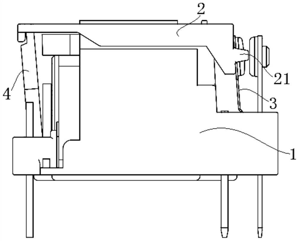
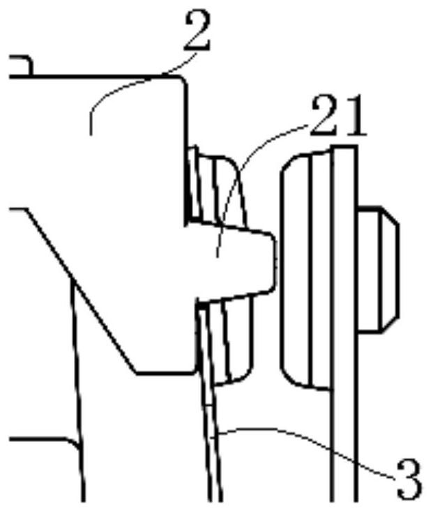
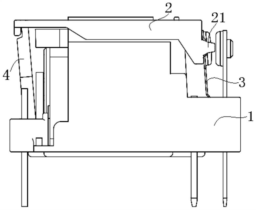
[0030] see image 3 , Figure 4 , Figure 5 , Image 6 , Figure 7 , Figure 8 , Figure 9 and Figure 10 As shown, the present invention is a push card assembly structure of a horizontal magnetic circuit relay, which includes a base 1 , a push card 2 and a moving reed 3 .

[0031] Specifically, based on the structural particularity of the horizontal magnetic circuit relay, the coil frame is mounted on the base 1 horizontally, and both sides of the base 1 in the width direction have enclosure plates 11 that protrude upward from both sides of the coil frame in the diameter direction. The base 1 may be an integrally formed structure with the coil frame, or may be a separate assembly structure.

[0032] Corresponding to the length directions of both ends of the coil former, the base 1 at one end of the coil former is equipped with a movable spring plate 3 , and the base 1 at the other end is equipped with an armature 4 . There are concave and notch-shaped moving spring in...

Embodiment 2

[0043] The present invention is a push card assembly structure of a horizontal magnetic circuit relay, which includes a base, a push card and a moving reed.

[0044] Specifically, based on the structural particularity of the horizontal magnetic circuit relay, the coil frame is horizontally assembled on the base, and both sides in the width direction of the base have enclosure plates that protrude upward from both sides of the coil frame in the diameter direction. The base may be an integrally formed structure with the coil frame, or may be a separate assembly structure.

[0045] Corresponding to the length directions of both ends of the coil frame, the base at one end of the coil frame is equipped with a movable spring plate, and the base at the other end is equipped with an armature. There are concave and notch-shaped moving spring insertion holes on the vertical sides of the upper width direction of the upper part of the moving reed, and each moving spring insertion hole has...

Embodiment 3

[0056] The present invention is a push card assembly structure of a horizontal magnetic circuit relay, which includes a base, a push card and a moving reed.

[0057] Specifically, based on the structural particularity of the horizontal magnetic circuit relay, the coil frame is horizontally assembled on the base, and both sides in the width direction of the base have enclosure plates that protrude upward from both sides of the coil frame in the diameter direction. The base may be an integrally formed structure with the coil frame, or may be a separate assembly structure.

[0058] Corresponding to the length directions of both ends of the coil frame, the base at one end of the coil frame is equipped with a movable spring plate, and the base at the other end is equipped with an armature. There are concave and notch-shaped moving spring insertion holes on the vertical sides of the upper width direction of the upper part of the moving reed, and each moving spring insertion hole has...


PUM


Abstract

The invention discloses a push card assembly structure of a horizontal relay, which comprises a movable spring plate assembled at one end of a coil frame, and a push card assembled between two ends of the coil frame. The push rod of the movable reed, the movable reed has a movable spring insertion hole that matches the push card, and the push rod at one end of the push card and the corresponding movable spring insertion hole on the movable reed are in an initial state in a ring. To the clearance fit. The invention effectively reduces the contact and mating chance and contact time between the push rod of the push card and the movable spring socket of the movable reed, and does not generate plastic dander in the mating space between the movable reed and the static reed, which is beneficial to ensure The horizontal magnetic circuit relay has stable and long-term service.

Description

technical field [0001] The invention relates to a relay, in particular to a push-card assembly structure of a horizontal magnetic circuit relay. Background technique [0002] The horizontal magnetic circuit relay is a common miniaturized relay structure. It forms a contact assembly structure at one end of the coil frame and an armature assembly structure at the other end. The contact assembly structure is used to assemble the moving reed and the static reed. , the armature assembly structure is used to assemble the armature and the compression spring, push the card to be arranged on the outer side of the coil along the length direction of both ends of the coil frame, and form an up-down corresponding fit with the base of the outer periphery of the coil frame, and push one end of the card to pass the convex The push rod forms a plug fit with the movable spring socket on the movable reed, and the other end forms a plug fit with the armature through the swing slot of the throug...

Claims


Application Information

Patent Timeline
Patent Type & Authority Patents(China)
IPC IPC(8): H01H50/64
CPCH01H50/64
Inventor 高山李奇峰
Owner SICHUAN HONGFA ELECTROACOUSTIC
Learn More