
A Residual Stress Detection Method Based on Load Measurement

A technology of residual stress and detection method, applied in the field of detection, can solve problems such as destructiveness and unsatisfactory effect, and achieve the effect of convenient application

Active Publication Date: 2017-04-19
ZHEJIANG TIANCHONG VEHICLE LAMP GROUP
View PDF3 Cites 0 Cited by
  • Summary
  • Abstract
  • Description
  • Claims
  • Application Information

AI Technical Summary

Problems solved by technology

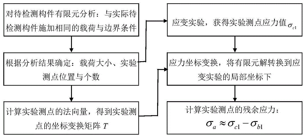
[0008] The present invention aims at the problem that the existing mechanical residual stress detection method is destructive to components and the effect is not very ideal, and proposes a non-destructive mechanical non-destructive detection method for simple measurement of component residual stress

Method used


Image

  • A Residual Stress Detection Method Based on Load Measurement
  • A Residual Stress Detection Method Based on Load Measurement
  • A Residual Stress Detection Method Based on Load Measurement

Examples


Embodiment approach 1

[0075] Such as image 3 As shown, the present invention provides an example of residual stress detection applied to injection molded products, which is characterized in that the injection molded parts have residual stress, so the detection method provided by the present invention is used for detection and calculation.

[0076] According to the basic steps provided by the present invention, the international system of units SI (basic dimension: mm, kg, s) is adopted, and the specific operation steps are as follows:

[0077] ① Determine the position of the loading point of the component to be tested, calculate and read the finite element solution σ' b1 .

[0078] Establish a computer geometric model for this application example product, and determine a pair of concentrated forces with a size of 20N, a direction perpendicular to the tangent plane of the loading point, and positions at points P1 and P2 through the debugging of loading calculations. The constraints are to impose ...


PUM


Abstract

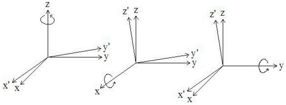
The invention belongs to the technical field of detection and discloses a load measurement-based residual stress detection method. The method comprises the following steps: establishing a computer geometric model of a to-be-detected member, applying restrictions to the model by a finite element method, performing linear elasticity finite element static analysis after a load is applied to a loading point, reading stress value sigma'<b1> of an experimental measuring point, and adjusting the position of the loading point or increasing the load so as to enable the maximum value of the component of the stress value sigma'<b1> to be larger than 0.1MPa if the maximum value of the component of the stress value sigma'<b1> is less than 0.1MPa; applying restrictions and a load same as those of the computer geometric model to the to-be-detected member, and performing a strain experiment to obtain a stress value sigma<c1> of the experimental measuring point; and transforming the sigma'<b1> under local coordinates of the experimental measuring point to obtain sigma<b1>, and subtracting sigma<b1> from sigma<c1> to obtain residual stress value sigma<a1> of the member at the experimental measuring point. According to the method disclosed by the invention, the surface of the member is not damaged in the detection process, and the problem that a member is damaged due to a conventional mechanical residual stress method is solved. In addition, the method is convenient, simple and flexible to apply.

Description

technical field [0001] The invention belongs to the technical field of detection and relates to a method for detecting mechanical residual stress, in particular to a method for mechanical non-destructive detection of residual stress of components. Background technique [0002] Many components of engineering structures will have more or less residual stress in the components due to processing and manufacturing reasons, or because of the needs of the assembly process, or bear the load exceeding the yield limit of their materials. The existence of residual stress, except for some special cases (such as the prestress of the pressure vessel helps to increase the bearing pressure), generally has a negative impact on the components, which not only reduces the mechanical properties such as the strength and fatigue of the structure, but also affects its safety in use. Sexuality, and more seriously, it will cause warping and cracking of components and lead to functional failure. [0...

Claims


Application Information

Patent Timeline
Patent Type & Authority Patents(China)
IPC IPC(8): G01N3/00G01L1/00
Inventor 刘红蒋兰芳陈先立杨哲人
Owner ZHEJIANG TIANCHONG VEHICLE LAMP GROUP
Learn More