Fixing device for motor on pumping unit

A technology of fixing devices and electric motors, which is applied in the field of oil pumping machinery, can solve the problems of potential safety hazards for workers, heavy motors, and occasional theft, etc., and achieve the effects of light displacement adjustment, easy popularization and application, and convenient displacement adjustment

Inactive Publication Date: 2014-11-12
李世銮
View PDF0 Cites 4 Cited by
  • Summary
  • Abstract
  • Description
  • Claims
  • Application Information

AI Technical Summary

Problems solved by technology

[0002] In the daily production of the oil field, the belt between the driving wheel of the motor and the auxiliary driving wheel of the balance weight is affected by the high temperature generated by friction or the high temperature of the external environment after a long period of continuous operation, and the phenomenon of belt relaxation is more likely to occur. The loose belt seriously affects the motor. The transmission effect between the driving wheel and the auxiliary driving wheel of the balance weight may even cause belt stripping, which brings certain safety hazards to the surrounding staff
Therefore, it is necessary to timely adjust the distance between the motor and the balance weight to tighten the belt, but because the motor is relatively heavy, and the motors on the oil field are usually directly fastened to the base bracket of the pumping unit with bolts to adjust the displacement. directly loosen the fastening bolts at the time, and rely on the staff's visual inspection to move the motor, which is time-consuming, laborious, and not accurate enough
In addition, the base of the motor is exposed outside the base bracket of the pumping unit, which is not safe enough. Illegal elements can directly remove the fastening bolts to complete theft and other damage. Theft of the motor occurs from time to time, which seriously affects the normal production of the oil field.

Method used


Image

  • Fixing device for motor on pumping unit
  • Fixing device for motor on pumping unit

Examples


Embodiment Construction

[0013] In order to clearly illustrate the technical features of the solution of the present invention, the present invention will be described below in conjunction with specific embodiments and accompanying drawings.

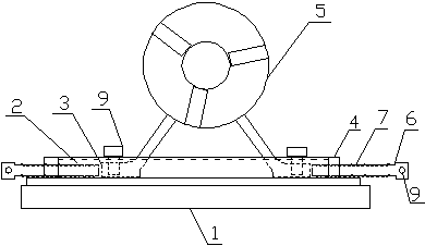
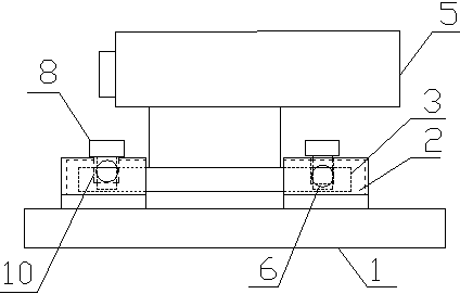
[0014] Depend on figure 1 , 2 It can be seen that there is a fixing device for a motor on a pumping unit. The structure of the fixing device is as follows: the base bracket 1 of the pumping unit is provided with two oppositely opened track grooves 2, the motor base 3 is embedded in the track groove 2, and the motor base 3 is Bolt holes are provided, track groove sealing blocks 4 are arranged at both ends of the track groove 2, and threaded holes are arranged on the sealing block 4, and the threaded holes in the threaded holes are connected with the motor displacement adjustment shaft 6.

[0015] A motor fixing groove 11 parallel to the track groove is provided at the middle position of the upper wall of the track groove 2 described above, and a fastening bolt 9...


PUM


Abstract

The invention relates to a fixing device for a motor on a pumping unit. The fixing device is structurally characterized in that two rail grooves with opposite openings are formed in a pumping unit base support, a motor base is embedded into the rail grooves, the two ends of the rail grooves are provided with rail groove sealing blocks, screw thread holes are formed in the sealing blocks, motor displacement adjusting shafts are connected into the screw thread holes through screw threads, the middles on the upper walls of the rail grooves are provided with motor fixing grooves parallel to the rail grooves, fastening bolts are arranged in the fixing grooves, the diameter of the bolt heads is larger than the width of the motor fixing grooves, the motor displacement adjusting shafts are provided with outer screw threads, and positioning holes are formed in the adjusting heads of the motor displacement adjusting shafts. The motor base is sealed into the two opposite rail grooves, the two ends of the motor base are sealed so that it can be ensured that a motor cannot be stolen, the displacement of the motor is adjusted through the screw threads of the displacement adjusting shafts, motor displacement adjustment is more convenient and accurate, the rail openings are formed in the upper walls of the rail grooves and can fix the position of the motor through the bolts, and position offset, caused by vibration, of the motor in the working process is prevented.

Description

technical field [0001] The invention relates to the technical field of oil pumping machines, in particular to a fixing device for an electric motor on an oil pumping machine. Background technique [0002] In the daily production of the oil field, the belt between the driving wheel of the motor and the auxiliary driving wheel of the balance weight is affected by the high temperature generated by friction or the high temperature of the external environment after a long period of continuous operation, and the phenomenon of belt relaxation is more likely to occur. The loose belt seriously affects the motor. The transmission effect between the driving wheel and the auxiliary driving wheel of the balance weight may even cause belt stripping, which brings certain safety hazards to the surrounding staff. Therefore, it is necessary to timely adjust the distance between the motor and the balance weight to tighten the belt, but because the motor is relatively heavy, and the motors on t...

Claims


Application Information

Patent Timeline
Patent Type & Authority Applications(China)
IPC IPC(8): H02K5/26H02K5/00
Inventor 李瑞国
Owner 李世銮
Why Eureka
Try Eureka