

Power circuit
A technology of power supply circuit and capacitor, applied in electrical components, regulating electrical variables, instruments, etc., can solve problems such as deterioration of conversion efficiency, and achieve the effect of improving the cross-regulation rate
- Summary
- Abstract
- Description
- Claims
- Application Information
AI Technical Summary
Problems solved by technology
Method used
Image

Examples
no. 1 Embodiment approach
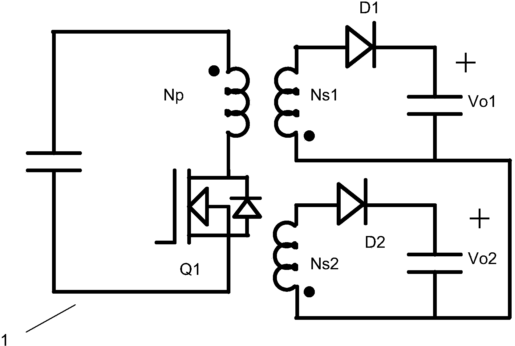
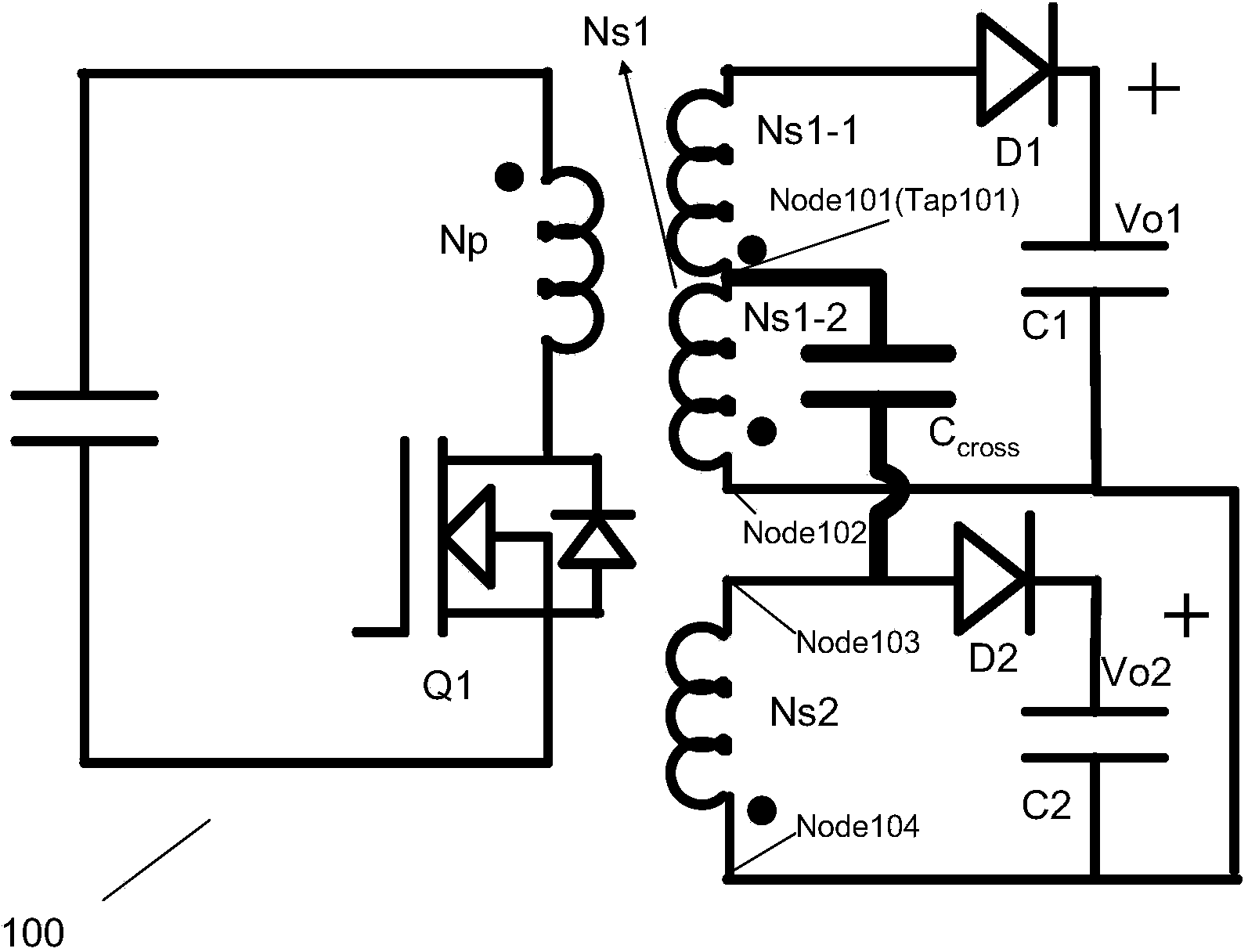
[0049] image 3 yes figure 1 In the shown flyback 2-output power supply device 1, a circuit with the characteristics involved in the present invention is added, that is, image 3 It is a diagram showing the power supply circuit 100 according to the first embodiment of the present invention. image 3 The power supply circuit 100 has a primary coil Np and a first output coil (secondary coil) Ns1 and a second output coil (secondary coil) Ns2 coupled to each other; a switching element Q1 connected in series with the primary coil Np; used to control the switching element A control circuit IC (not shown) of Q1; a rectifying element (diode) D1 for supplying power to the first output terminal Vo1 and a rectifying element (diode) D2 for supplying power to the second output terminal Vo2. The winding directions of the primary coil Np and the secondary coils Ns1 and Ns2 are opposite, thereby forming a flyback power supply device. Here, in the first output coil Ns1, the part (node Nod...
no. 2 Embodiment approach
[0060] Figure 8A It is a diagram showing the power supply circuit 200 according to the second embodiment of the present invention. The power supply circuit 200 according to the second embodiment is mainly different from the power supply circuit 100 according to the first embodiment in that the first output coil (secondary coil) Ns1 and the second output coil (secondary coil) Ns2 Both draw center taps.
[0061] The power supply circuit 200 is provided with a primary coil Np and a first output coil (secondary coil) Ns1 and a second output coil (secondary coil) Ns2 coupled to each other; a switching element Q1 connected in series with the primary coil Np; for controlling the switching element Q1 A control circuit IC (not shown in the figure); a rectifying element (diode) D1 for supplying power to the first output terminal Vo1 and a rectifying element (diode) D2 for supplying power to the second output terminal Vo2. The winding directions of the primary coil Np and the secondar...
no. 3 Embodiment approach
[0070] Figure 9 It is a figure which shows the power supply circuit 300 which concerns on 3rd Embodiment of this invention. The main difference between the power supply circuit 300 according to the third embodiment and the power supply circuit 200 according to the second embodiment is that the second output coil (secondary coil) Ns2 is connected to the first output coil (secondary coil) by adding an additional coil. Coil) Ns1 connected.
[0071] The power supply circuit 300 is provided with a primary coil Np and a first output coil (secondary coil) Ns1 and a second output coil (secondary coil) Ns2 coupled to each other; a switching element Q1 connected in series with the primary coil Np; for controlling the switching element Q1 A control circuit IC (not shown in the figure); a rectifying element (diode) D1 for supplying power to the first output terminal Vo1 and a rectifying element (diode) D2 for supplying power to the second output terminal Vout. The winding directions of...
PUM
 Abstract
Description
Claims
Application Information