A Multi-output Flyback Converter

A flyback converter and multi-output technology, which is applied in the direction of output power conversion device, DC power input conversion to DC power output, instruments, etc., can solve the problem of unsatisfactory cross-regulation effect, complex circuit structure, and manufacturing cost. Advanced problems, to achieve the effect of easy debugging and measurement, simple circuit structure, and elimination of voltage drift

Active Publication Date: 2021-01-19
BEIJING MECHANICAL EQUIP INST
View PDF7 Cites 0 Cited by
  • Summary
  • Abstract
  • Description
  • Claims
  • Application Information

AI Technical Summary

Problems solved by technology

[0005] In view of the above analysis, the embodiment of the present invention aims to provide a multi-output flyback converter to solve the problems of unsatisfactory improvement of cross regulation rate, complex circuit structure and high manufacturing cost in the prior art

Method used


Image

  • A Multi-output Flyback Converter
  • A Multi-output Flyback Converter
  • A Multi-output Flyback Converter

Examples


Embodiment 1

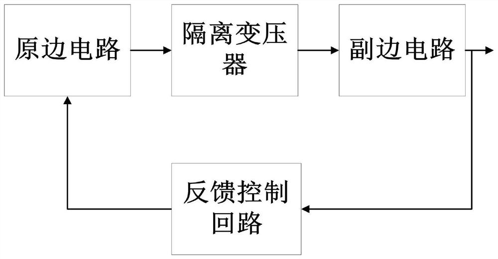
[0054]A specific embodiment of the present invention discloses a multi-output flyback converter, such asfigure 1 Shown, including isolation transformer, primary circuit, secondary circuit and feedback control loop. Among them, the secondary side circuit includes the main output loop and N-way secondary output loop; N≥1.

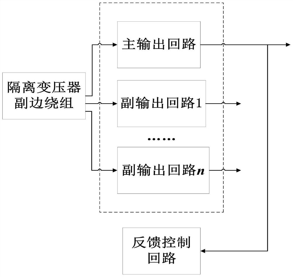
[0055]Specifically, in the secondary side circuit, such asfigure 2 As shown, the secondary side of the isolation transformer includes N+1 windings, one of which is used as the main output loop, and the other N windings are used as the secondary output loop.

[0056]The main output loop includes freewheeling diodes and capacitors. The negative pole of the secondary winding of the isolation transformer corresponding to the main output loop is connected to the positive pole of the main output loop output terminal through a freewheeling diode, and the positive pole of the winding is connected to the negative pole of the main output loop output terminal and grounded; the posi...

Embodiment 2

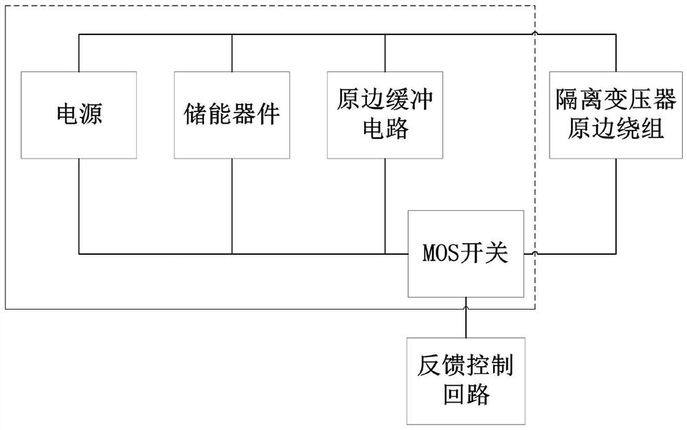
[0071]Improved on the basis of the above-mentioned embodiments, the primary side circuit includes a power supply, an energy storage device, a primary side buffer circuit, and a MOS switch.

[0072]In the primary circuit, such asimage 3 As shown, the positive pole of the power supply is connected to one end of the energy storage device, the input end of the primary buffer circuit, and the positive pole of the primary winding of the isolation transformer. The negative pole of the power supply is connected to the other end of the energy storage device, the output end of the primary buffer circuit, and MOS The source of the switch is connected; the drain of the MOS switch is connected to the negative electrode of the isolation transformer; the gate of the MOS switch is used as the control terminal of the primary circuit and is connected to the output terminal of the feedback control loop. In the primary side circuit, the power supply is used to provide electrical energy for the energy stor...


PUM


Abstract

The invention relates to a multi-output flyback converter, belonging to the technical field of flyback converters, which solves the problems that the prior art is not ideal in improving the cross regulation rate, the circuit structure is complex and the manufacturing cost is high. The flyback converter comprises an isolation transformer, a primary side circuit, a secondary side circuit and a feedback control loop. Wherein, the secondary side circuit comprises a main output loop and an N-way secondary output loop; N >= 1. The main output circuit comprises a freewheeling diode and a capacitor, and the secondary output circuit comprises an improved resistor, a freewheeling diode and a capacitor. The feedback control loop collects the output signal of the main output loop as the feedback signal, and outputs the driving signal to control the primary circuit after processing, so as to reduce the energy loss caused by the leakage inductance and improve the circuit cross-adjustment rate. The flyback converter has the advantages of simple structure, easy parameter calculation, elimination of high voltage drift, convenience in use, small volume, light weight and low cost, and is suitable forengineering application.

Description

Technical field[0001]The invention relates to the technical field of switching power supplies, in particular to a multi-output flyback converter.Background technique[0002]Flyback converter has the advantages of simple structure, small size, low cost, no filter inductance, and isolation output. By adding additional secondary windings, multiple outputs of the converter can be realized, and it is widely used in low-power DC applications. Occasions, such as auxiliary power supplies for chargers, set-top boxes, and large power supplies.[0003]When a flyback converter works as a switching power supply, it is often necessary to provide a stable output voltage or current, and make the voltage regulation rate or load regulation rate of the circuit meet the design index, so the circuit needs to be closed-loop control to resist input voltage disturbance The impact of external disturbances such as load disturbances on the output. In a flyback converter circuit, the sampling signal output from th...

Claims


Application Information

Patent Timeline
Patent Type & Authority Patents(China)
IPC IPC(8): H02M3/335
CPCH02M3/33561
Inventor 王浩宇赵鑫郭鑫
Owner BEIJING MECHANICAL EQUIP INST
Why Eureka
Try Eureka