Automatic fluid metering device for tight sandstone relative permeability experiment and use method of automatic fluid metering device

An automatic metering and tight sandstone technology, which is applied in the directions of surveying, earthwork drilling and production, wellbore/well components, etc., and can solve the problems of unacceptable metering error and less liquid phase, etc.

Pending Publication Date: 2022-05-10
CHINA NAT OFFSHORE OIL CORP +1
View PDF0 Cites 0 Cited by
  • Summary
  • Abstract
  • Description
  • Claims
  • Application Information

AI Technical Summary

Problems solved by technology

[0003] The present invention overcomes the deficiencies in the prior art, aiming at the gas-water phase permeability of unconventional low-permeability rock cores, the amount of liquid phase of various gas-liquid displacements is very small, and even a small amount of liquid droplets or even gas splashed on the glass tube The problem that the measurement error caused by the trace amount of water is not allowed, provides an automatic measurement device for tight sandstone relative permeability experiment fluid and its use method. The device adds high-precision gas measurement and is equipped with high-precision micro-pressure sensors. The micro-pressure sensor senses the small pressure of the gas at the outlet of the core holder, and the signal is amplified to drive the metering pump. When the pressure increases, the air pump pumps, and when the suction decreases, the pump is stopped, and a stable closed-loop control is formed between the micro-pressure sensor and the metering pump. , to achieve high-precision measurement

Method used


Image

  • Automatic fluid metering device for tight sandstone relative permeability experiment and use method of automatic fluid metering device
  • Automatic fluid metering device for tight sandstone relative permeability experiment and use method of automatic fluid metering device
  • Automatic fluid metering device for tight sandstone relative permeability experiment and use method of automatic fluid metering device

Examples


Embodiment 1

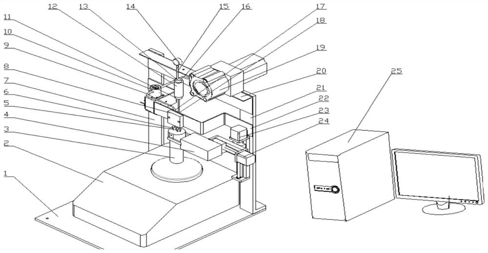
[0025] An automatic fluid metering device for tight sandstone phase permeability experiments, including a base plate 1, a balance 2, a micro-pressure sensor 14, a gas metering pump 19 and a data acquisition system 25,

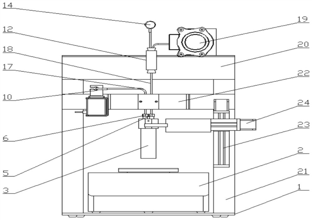
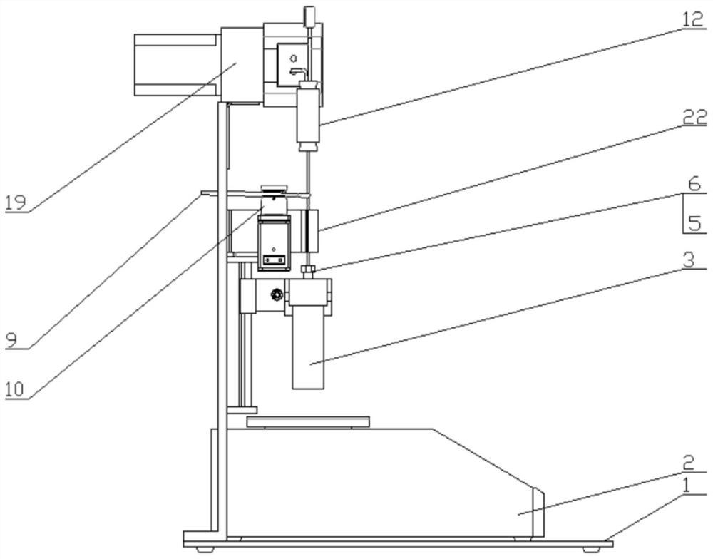
[0026] The balance 2 is arranged on the upper surface of the bottom plate 1, and the left column 7 and the right column 21 are respectively fixed on the bottom plate 1 on both sides of the balance 2. The head end of the left column 7 and the head end of the right column 21 are connected by a beam 20, and the gas metering The pump 19 is installed on the crossbeam 20. A pipeline fixing frame 22 is arranged between the left column 7 and the right column 21 below the beam 20. The pipeline fixing frame 22 adopts a U-shaped structure. The drying bottle inlet pipe 17 and the drying bottle outlet pipe 18, the drying bottle 3 is arranged directly below the drying bottle inlet pipe 17 and the drying bottle outlet pipe 18, and a through hole is provided on the drying bottl...

Embodiment 2

[0028] On the basis of Embodiment 1, a Y-axis mechanical arm 23 is also installed in the middle of the right column 21. The Y-axis mechanical arm 23 can move along the vertical direction, and an X-axis mechanical arm 24 is slidably installed on the Y-axis mechanical arm 23. The X-axis mechanical arm 24 can move along the horizontal direction, and the movable end of the X-axis mechanical arm 24 is equipped with a manipulator 4. The manipulator 4 is used to grab the drying bottle 3, so as to realize that the grabbing drying bottle 3 is inserted upward into the drying bottle inlet pipe 17 and drying bottle outlet pipe 18, or pull down to break away from drying bottle inlet pipe 17 and drying bottle outlet pipe 18, and place the purpose on the balance.

[0029]A first pinch valve 8 and a second pinch valve 10 are arranged on the pipeline fixing frame 22, and the first pinch valve 8 is installed in the middle part of the U-shaped structure of the pipeline fixing frame 22 for connect...

Embodiment 3

[0031] On the basis of Embodiment 2, an inlet self-sealing pressure cap 6 and an outlet self-sealing pressure cap 5 are respectively arranged on the through holes of the drying bottle 3, and a central hole is provided on the inlet self-sealing pressure cap 6 and the outlet self-sealing pressure cap 5, and the inlet The central hole of the self-sealing pressure cap 6 is arranged opposite to the inlet pipe 17 of the drying bottle, and the central hole of the outlet self-sealing pressure cap 5 is arranged opposite to the outlet pipe 18 of the drying bottle.

[0032] The lower plug 11 of the air chamber is arranged at the inlet end of the buffer air chamber 12, the outlet end of the outlet pipe 18 of the drying bottle penetrates the lower plug 11 of the air chamber and extends into the buffer air chamber 12, and an air chamber is arranged at the outlet end of the buffer air chamber 12 The upper plug 13, the micro-pressure sensor pressure introduction pipe 14 and the gas metering pu...


PUM


Abstract

The invention provides an automatic fluid metering device for a tight sandstone relative permeability experiment and a using method of the automatic fluid metering device. A drying bottle inlet pipe and a drying bottle outlet pipe are arranged in the middle of a U-shaped structure of a pipeline fixing frame, and the outlet end of the drying bottle inlet pipe is communicated with the inlet end of an inlet hose; the outlet end of the drying bottle outlet pipe extends into the inlet end of the buffer gas chamber, the outlet end of the buffer gas chamber is respectively provided with a micro-pressure sensor pressure guide pipe and a gas metering pump inlet pipe, the buffer gas chamber is connected with the micro-pressure sensor through the micro-pressure sensor pressure guide pipe, and the buffer gas chamber is connected with the gas metering pump through the gas metering pump inlet pipe. According to the device, the micro-pressure sensor senses the micro pressure of gas at an outlet of the core holder, the micro pressure is amplified to drive the metering pump, the gas pump sucks when the pressure is increased, the pressure is reduced when the gas sucks, the pump is stopped, stable closed-loop control is formed between the micro-pressure sensor and the metering pump, high-precision metering is realized, and the metering resolution can reach 0.1 ml.

Description

technical field [0001] The invention relates to the technical field of oilfield fluid experiments, in particular to an automatic fluid metering device for tight sandstone relative permeability experiments and a method for using the same. Background technique [0002] The gas-water relative permeability curve obtained from the tight sandstone gas phase permeability experiment can quantitatively evaluate the production effect of water-producing gas wells, and realizes an effective means for quantitatively evaluating the productivity, production, final cumulative gas production and recovery of water-producing gas wells. In the gas-water phase permeability test of tight sandstone cores, firstly, the measured liquid is very small, and part of the liquid sticks to the glass tube, which brings systematic errors to the measurement, so various existing metering devices on the market are not competent; Use a desiccant to absorb moisture, and then use a balance to weigh it. However, du...

Claims


Application Information

Patent Timeline
Patent Type & Authority Applications(China)
IPC IPC(8): E21B47/00
CPCE21B47/00
Inventor 李洋冰马立涛刘成陈鑫胡维强刘玉明胡云亭王磊
Owner CHINA NAT OFFSHORE OIL CORP
Why Eureka
Try Eureka