Rapid generation device of gaseous chlorine dioxide

A chlorine dioxide, rapid generation technology, applied in the direction of chlorine dioxide, chlorine oxide, etc., can solve the problems of narrow overflow air duct, low ventilation flow, heavy weight, etc., to achieve increased diffusion rate, large ventilation flow, and small wind resistance Effect

Pending Publication Date: 2021-04-09
北京诚益通科技有限公司
View PDF0 Cites 0 Cited by
  • Summary
  • Abstract
  • Description
  • Claims
  • Application Information

AI Technical Summary

Problems solved by technology

[0002] At present, the overflow air channel of the existing gas chlorine dioxide generators on the market is narrow, which cannot guarantee the rapid overflow of chlorine dioxide gas after generation; in addition, the main air channel is arranged on the side of the beaker-type reaction chamber, with large wind resistance and low ventilation flow rate. And the equipment is bulky and heavy
The existing gaseous chlorine dioxide generating device adopts a single beaker-type reaction chamber. Due to the limitation of reaction conditions, the amount of reagents involved in a single reaction cannot be too large, resulting in the limitation of the total amount of gaseous chlorine dioxide produced; in addition, the existing gaseous chlorine dioxide The generating device adopts a single beaker-type reaction chamber. Only after the current batch of reagents are completely reacted and the waste liquid is discharged, can new reagents be added to carry out the next batch of reactions. There is a time interval in the middle, and the gas dioxide cannot be continuously produced. Chlorine, the amount of gas generated per unit time fluctuates greatly; finally, the reaction temperature of existing gas chlorine dioxide generators is uncontrollable, and working in a low temperature environment will reduce the rate of gas chlorine dioxide generation

Method used


Image

  • Rapid generation device of gaseous chlorine dioxide
  • Rapid generation device of gaseous chlorine dioxide
  • Rapid generation device of gaseous chlorine dioxide

Examples


Embodiment Construction

[0027] The specific embodiments of the present invention will be described in detail below in conjunction with the accompanying drawings, but it should be understood that the protection scope of the present invention is not limited by the specific embodiments.

[0028] Unless expressly stated otherwise, throughout the specification and claims, the term "comprise" or variations thereof such as "includes" or "includes" and the like will be understood to include the stated elements or constituents, and not Other elements or other components are not excluded.

[0029] In this document, for the convenience of description, spatially relative terms, such as "below", "below", "lower", "above", "above", "upper", etc., may be used to describe the relationship between one element or feature and another. The relationship of elements or features in the drawings. It will be understood that the spatially relative terms are intended to encompass different orientations of the item in use or o...


PUM


Abstract

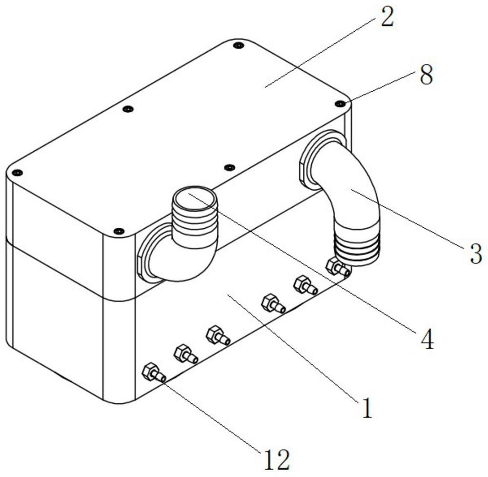
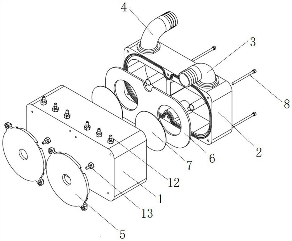
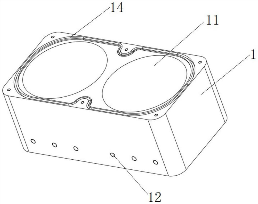
The invention relates to a rapid generation device of gaseous chlorine dioxide, which is characterized in that a cavity upper cover is fixedly arranged at the top of a cavity, a reaction cavity is formed in the cavity, a reactant injection port is formed in the side wall of the reaction cavity, a cavity clamping plate is horizontally arranged at the joint of the cavity and the cavity upper cover, an air inlet and an air outlet are formed in the side wall of the cavity upper cover, a cavity air duct is arranged between the air inlet and the air outlet in the cavity upper cover, a blocking cap mounting column which corresponds to the center of the cavity and extends towards the cavity is arranged on the top wall of the cavity upper cover, the lower end of a blocking cap is suspended at the upper part of the reaction cavity and is arranged below a clamping plate through hole, and the upper end of the blocking cap penetrates through the clamping plate through hole to be connected with the blocking cap mounting column. By arranging a plurality of reaction cavities, the metering of a reactant which integrally participates in reaction in the cavities is improved, and gaseous chlorine dioxide is generated more efficiently, continuously and stably. The cavity air duct is arranged above the reaction cavity, so that the air resistance is small, the ventilation flow is large, and the diffusion rate of gaseous chlorine dioxide is greatly improved.

Description

technical field [0001] The invention relates to the technical field of disinfection and sterilization equipment, in particular to a rapid generation device for gaseous chlorine dioxide. Background technique [0002] At present, the overflow air channel of the existing gas chlorine dioxide generators on the market is narrow, which cannot guarantee the rapid overflow of chlorine dioxide gas after generation; in addition, the main air channel is arranged on the side of the beaker-type reaction chamber, with large wind resistance and low ventilation flow rate. And the equipment is bulky and heavy. The existing gaseous chlorine dioxide generating device adopts a single beaker-type reaction chamber. Due to the limitation of reaction conditions, the amount of reagents involved in a single reaction cannot be too large, resulting in the limitation of the total amount of gaseous chlorine dioxide produced; in addition, the existing gaseous chlorine dioxide The generating device adopts...

Claims


Application Information

Patent Timeline
Patent Type & Authority Applications(China)
IPC IPC(8): C01B11/02
CPCC01B11/022
Inventor 邓元龙李洲
Owner 北京诚益通科技有限公司
Why Eureka
Try Eureka