
Improvements in controlling internal combustion engine emissions

An internal combustion engine, engine technology, applied in the direction of internal combustion piston engine, combustion engine, engine control, etc., can solve the problem of effective working delay of the catalytic converter, and achieve the effect of short duration

Active Publication Date: 2014-11-12
JAGUAR LAND ROVER LTD
View PDF7 Cites 3 Cited by
  • Summary
  • Abstract
  • Description
  • Claims
  • Application Information

AI Technical Summary

Problems solved by technology

Effective operation of the catalytic converter may be delayed when the vehicle is started in relatively cold conditions

Method used


Image

  • Improvements in controlling internal combustion engine emissions
  • Improvements in controlling internal combustion engine emissions
  • Improvements in controlling internal combustion engine emissions

Examples


Embodiment Construction

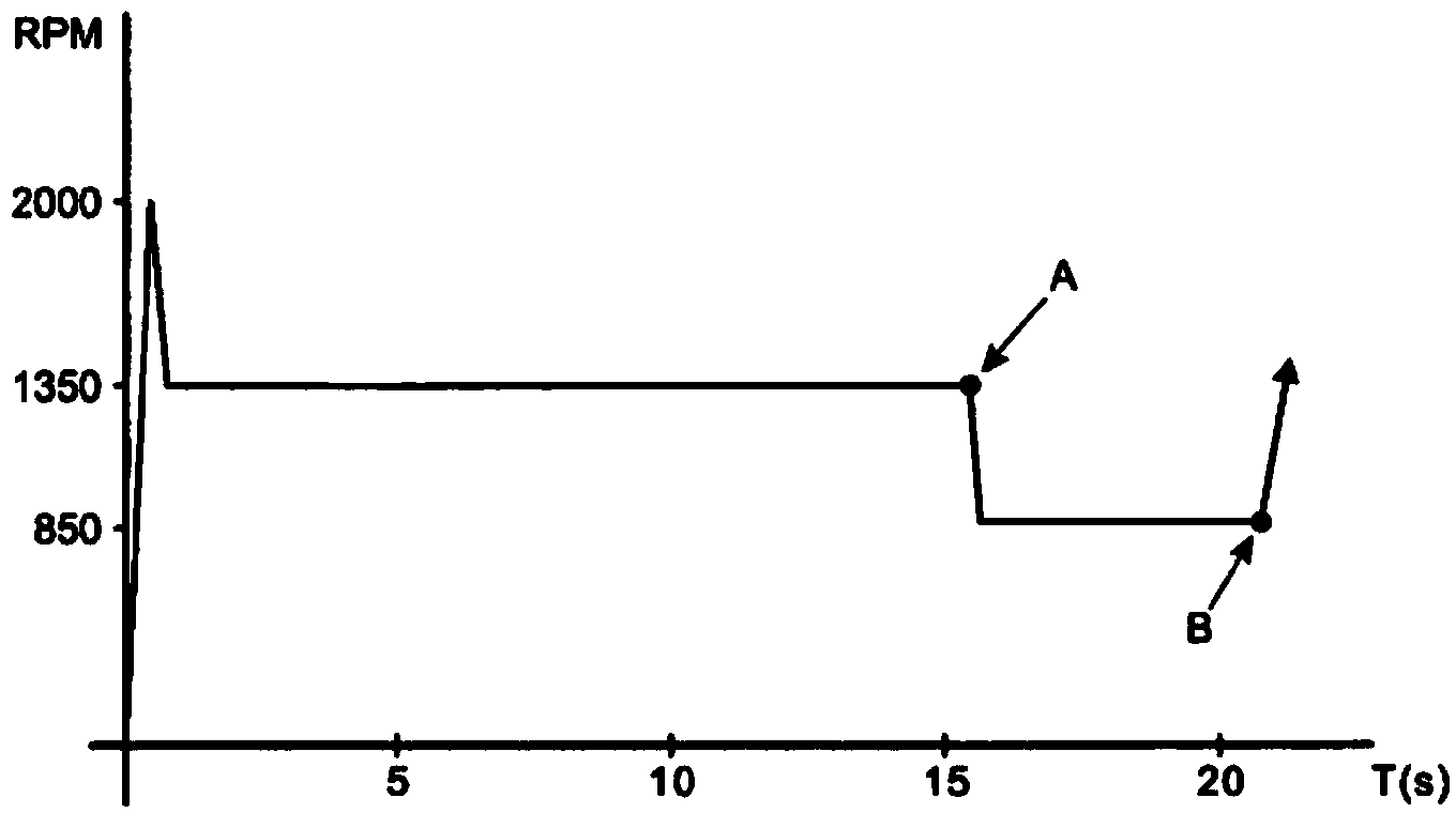
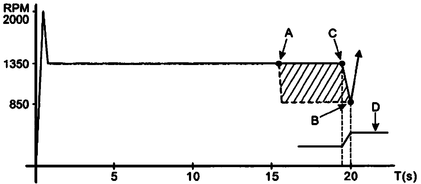
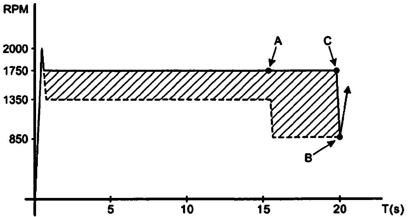
[0032] refer to figure 1 A conventional engine cold start for an electronically controlled internal combustion engine typically has an initial engine speed of 2000 rpm (revolutions per minute), which drops almost immediately to a fast idle of 1350 rpm. The fast idle is maintained from start up until about 15 seconds in order, for example, to stabilize the combustion. When the driveline is selected and engaged, the idle speed then decreases at A to approximately 850 rpm, which is an appropriate speed for the driver to drive away smoothly and gradually. The start of the vehicle - ie drive away - is at B, usually after the next time period of about 5 seconds.

[0033] In any automatic or automated powertrain, the controller will select the appropriate starting gear in response to driver commands. Typically, the driver will select a low or drive gear out of park or neutral. Typically, starting of the vehicle's engine is inhibited unless Park is selected, and activation of the d...


PUM


Abstract

Disclosed is an engine control method for a vehicle having an electronically controlled drive line such as an electronic multi-speed transmission with an automatic gear box. The method of operation comprises the steps of turning on the engine and then keeping the engine revs high whilst an engine is idling and not connected to a transmission system, for instance whilst the neutral position is selected. The high idle speed is maintained on sensing that the gear select is moved from neutral to drive and the controller delays dropping the engine idle speed and engaging the drive line until the wheel brake is removed. Sensors may be provided to detect release of the wheel brakes and gear position. The method is used to provide a high engine operating speed on engine start up and / or warm up to ensure that the engine heats up rapidly so that the hot exhaust fumes can be used to heat a catalytic convertor to bring it to its active operating temperature.

Description

technical field [0001] The present invention relates to improvements in the control of emissions from internal combustion engines, in particular to more rapidly initiating the treatment of exhaust gases at cold start of the engine. Aspects of the invention relate to a method and a vehicle. Background technique [0002] Vehicle emissions legislation sets certain limits on the emission of harmful gases in the exhaust stream of internal combustion engines. Typically, a catalytic converter is located in a vehicle's exhaust system, which works to chemically convert harmful gases into relatively benign alternatives. [0003] Catalytic converters require a minimum temperature in order to operate efficiently, which can be achieved for short periods of time by heat transfer from the hot exhaust flow. When the vehicle is started in relatively cold conditions, effective operation of the catalytic converter may be delayed. It is desirable to reduce this delay to minimize the emission...

Claims


Application Information

Patent Timeline
IPC IPC(8): B60W30/194B60W10/06B60W10/11F02D41/02F02D41/08
CPCF02D2200/0802B60W10/06F02D41/08B60W30/194B60W10/11B60W2710/065B60W2540/12B60W2540/16Y02T10/54B60W2550/142F02D41/0225B60W2540/10Y02T10/26B60W30/18027F02D41/0255B60W2552/15Y02T10/12Y02T10/40B60W2710/0644F02D41/021F02D41/0215F02D41/022F02D41/024F02D41/062F02D41/064F02D41/068F02D41/16B60W30/18B60W30/18054
Inventor 罗布·耶格尔尼克·威克大卫·海登西蒙·贾维斯
Owner JAGUAR LAND ROVER LTD
Learn More