

Drawing device and drawing program
A technology of picture elements and candidate lines, applied in the fields of drawing devices and drawing programs, can solve problems such as intermediate color bleeding, and achieve the effect of reducing pollution and improving recognition.
- Summary
- Abstract
- Description
- Claims
- Application Information
AI Technical Summary
Problems solved by technology
Method used
Image

Examples
Embodiment approach 1
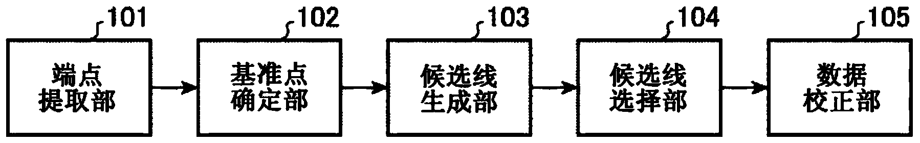
[0026] figure 1 It is a functional block diagram of the drawing device according to Embodiment 1.
[0027] As shown in the figure, the drawing device according to this embodiment includes an end point extracting unit 101 , a reference point specifying unit 102 , a candidate line generating unit 103 , a candidate line selecting unit 104 , and a data correcting unit 105 . In addition, the drawing device is realized by a computer, and the endpoint extracting unit 101 to the data correcting unit 105 are composed of software corresponding to their respective functions and hardware such as a CPU and a memory for executing the software. Alternatively, at least one functional unit among the endpoint extraction unit 101 to the data correction unit 105 may be constituted by dedicated hardware.
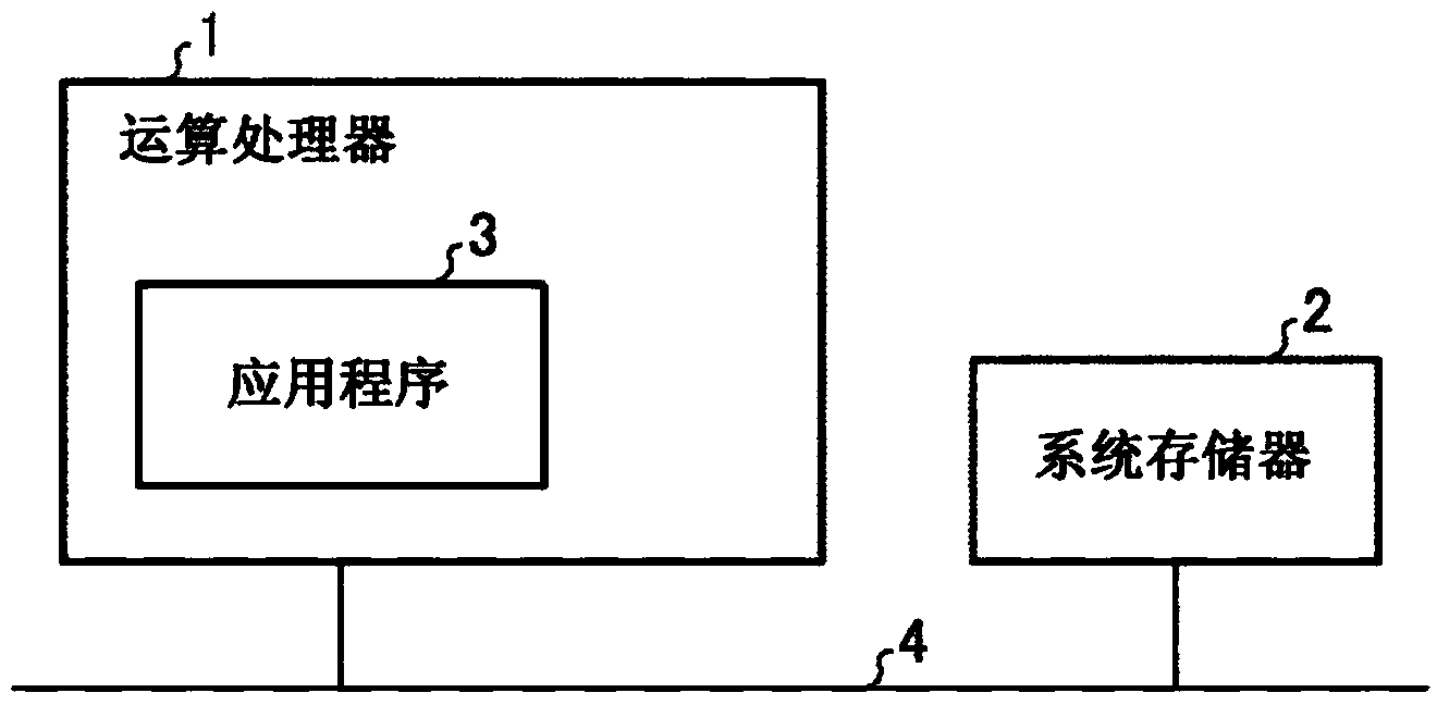
[0028] figure 2 It is a structural diagram of a computer system that implements a drawing device.
[0029] The illustrated computer system has an arithmetic processor 1 , a system memory 2 ,...
Embodiment approach 2
[0042] In the oblique line bleeding improvement method performed in Embodiment 1, since correction of oblique lines in characters requires multiple distance calculations, there is a problem that the amount of calculation is large. Therefore, in Embodiment 2, an example was shown in which blurring is improved by correcting the start point and end point of oblique lines toward the center of the pixel pixel to speed up oblique line correction processing.
[0043] Figure 8 It is a functional block diagram showing the drawing device according to the first embodiment.
[0044] The drawing device according to Embodiment 2 includes an endpoint extraction unit 201 , an endpoint position correction unit 202 , and a data correction unit 203 . Similar to the endpoint extraction unit 101 in Embodiment 1, the endpoint extraction unit 201 extracts the pixel coordinates of the start point and end point of the oblique line. The end point position correction unit 202 corrects the positions o...
Embodiment approach 3
[0048] Embodiment 3 is an example of improving the bleeding by using curve data as an object. Figure 9 A functional block diagram of the drawing device according to Embodiment 3 is shown in .
[0049] The drawing device according to Embodiment 3 includes a curve data extraction unit 301 , an end point position correction unit 302 , a candidate line generation unit 303 , a straight line division unit 304 , a reference point determination unit 305 , a candidate line selection unit 306 , and a data correction unit 307 .
[0050] The curve data extraction unit 301 is a functional unit that extracts the start point, end point, and control point of the curve data. The end point position correction unit 302 is a functional unit that corrects the positions of the start point and the end point extracted by the curve data extraction unit 301 to the center of the pixel pixel. The candidate line generating unit 303 is a functional unit that generates a candidate line of a curve based on...
PUM
 Abstract
Description
Claims
Application Information