Spherical Grinder

A grinding machine and grinding head technology, applied in the grinding field, can solve the problems of low efficiency, time-consuming and labor-intensive, etc., and achieve the effect of avoiding direct transmission, reducing production costs, and achieving the best grinding effect

Active Publication Date: 2017-01-18
JIANGSU YUANYE HYDRAULIC MACHINERY
View PDF6 Cites 3 Cited by
  • Summary
  • Abstract
  • Description
  • Claims
  • Application Information

AI Technical Summary

Problems solved by technology

It is inefficient and time consuming to do so

Method used


Image

  • Spherical Grinder
  • Spherical Grinder
  • Spherical Grinder

Examples


Embodiment Construction

[0021] The following will clearly and completely describe the technical solutions in the embodiments of the present invention with reference to the drawings in the embodiments of the present invention.

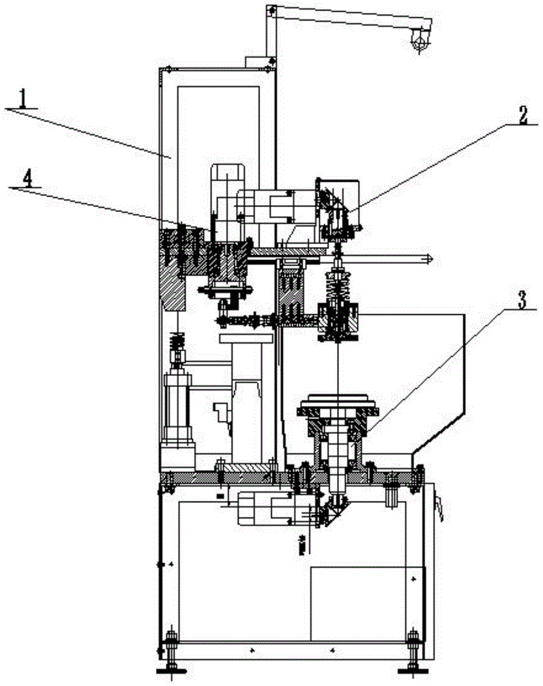
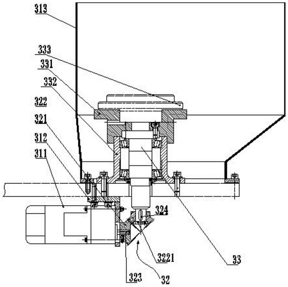
[0022] This example Figure 1 to Figure 5 A spherical grinding machine is shown, which includes a frame 1, which is characterized in that an upper grinding head assembly 2 is arranged above the frame 1, and a lower grinding head assembly is arranged corresponding to the lower part of the upper grinding head assembly 2. 3. The upper grinding head assembly 2 and the lower grinding head assembly 3 move relative to each other to grind the workpiece surface, and the upper grinding head assembly 2 is connected with an upper grinding head assembly swing mechanism 4, wherein:

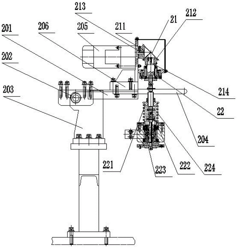
[0023] The upper grinding head assembly 2 includes a flat drag 201, the flat drag 201 is rotated on the supporting plate bracket 203 through the supporting plate rotating ear 202, and one end of the flat draggi...


PUM


Abstract

The invention provides a ball grinder. The ball grinder comprises a machine frame. An upper grinding head assembly is arranged above the machine frame. A lower grinding head assembly is correspondingly arranged below the upper grinding head assembly. The upper grinding head assembly and the lower grinding head assembly move relatively to grind the surface of a workpiece. The upper grinding head assembly is connected with an upper grinding head assembly swing mechanism. The ball grinder is a novel grinder capable of effectively grinding the workpiece and guaranteeing the grinding quality.

Description

technical field [0001] The invention relates to the field of grinding, in particular to a spherical grinding machine. Background technique [0002] There are many types of grinders according to their usage. For example, the grinding machine used to grind the edge of the workpiece, the grinding machine for grinding the surface of the workpiece, no matter what kind of grinding machine, its working principle is to grind the workpiece itself through the power part to drive the grinding part. The spherical grinding machine grinds the workpiece through a spherical or hemispherical grinding head. In the traditional grinding machine, the motor is set above the upper grinding head and below the lower grinding head, and the motor shaft is connected with the transmission shaft of the grinding head to drive the movement of the upper and lower molds, and the grinding head parts are set in the mold to follow the movement. Grinding of workpieces. The advantage of the direct connection b...

Claims


Application Information

Patent Timeline
Patent Type & Authority Patents(China)
IPC IPC(8): B24B37/025B24B37/34B24B47/12
CPCB24B37/025B24B37/34B24B47/12
Inventor 马建明
Owner JIANGSU YUANYE HYDRAULIC MACHINERY
Why Eureka
Try Eureka