
Locator and method for monitoring radioactive source

A radioactive source and locator technology, applied in the field of radioactive source monitoring, can solve problems such as deviation, achieve the effect of eliminating phase difference and improving positioning accuracy

Inactive Publication Date: 2014-11-19
BEIJING NOVEL MEDICAL EQUIP LTD
View PDF4 Cites 5 Cited by
  • Summary
  • Abstract
  • Description
  • Claims
  • Application Information

AI Technical Summary

Problems solved by technology

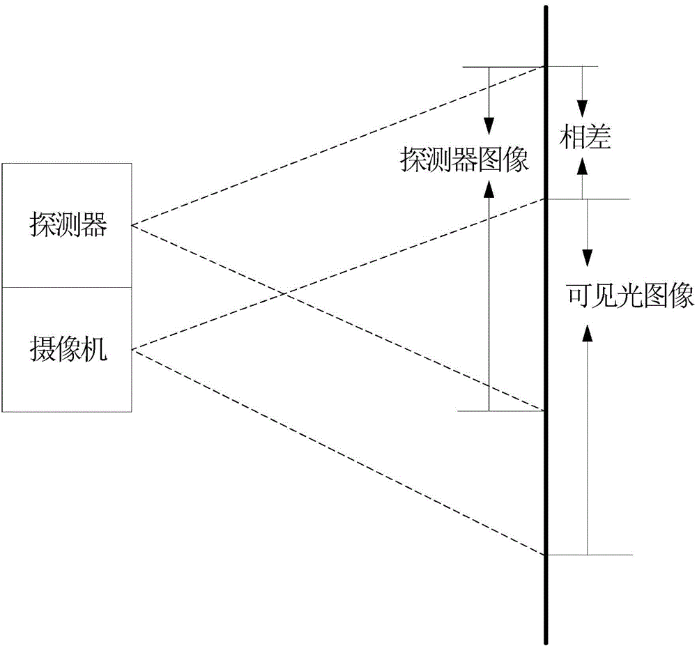
The detector image is obtained by the detector using radiation detection technology, and the visible light image is obtained by the camera through video surveillance technology, but in the monitoring screen, there is a certain deviation between the radioactive source position calibrated by radiation detection and the radioactive source position in the video surveillance screen

Method used


Image

  • Locator and method for monitoring radioactive source
  • Locator and method for monitoring radioactive source
  • Locator and method for monitoring radioactive source

Examples


Embodiment Construction

[0024] Embodiments of the present invention are described in detail below, examples of which are shown in the drawings, wherein the same or similar reference numerals designate the same or similar elements or elements having the same or similar functions throughout. The embodiments described below by referring to the figures are exemplary only for explaining the present invention and should not be construed as limiting the present invention.

[0025] In describing the present invention, it should be understood that the terms "center", "longitudinal", "transverse", "upper", "lower", "front", "rear", "left", "right", " The orientations or positional relationships indicated by "vertical", "horizontal", "top", "bottom", "inner" and "outer" are based on the orientations or positional relationships shown in the drawings, and are only for the convenience of describing the present invention and Simplified descriptions, rather than indicating or implying that the device or element refe...


PUM


Abstract

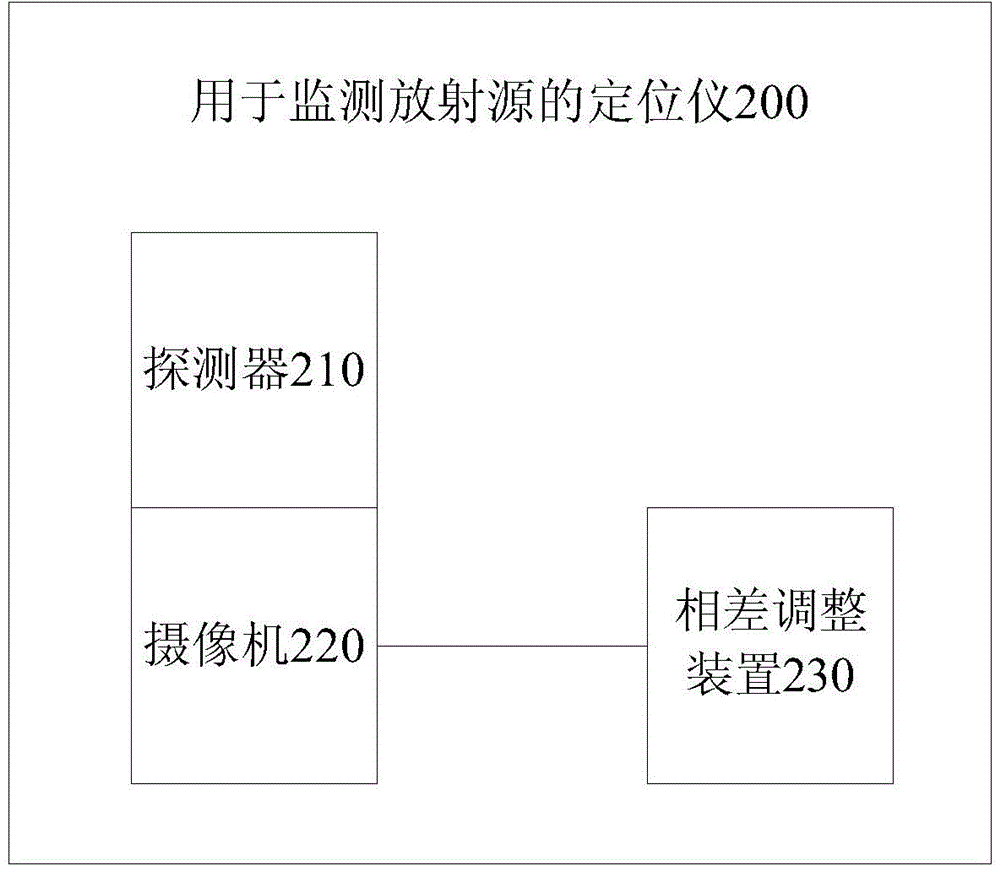
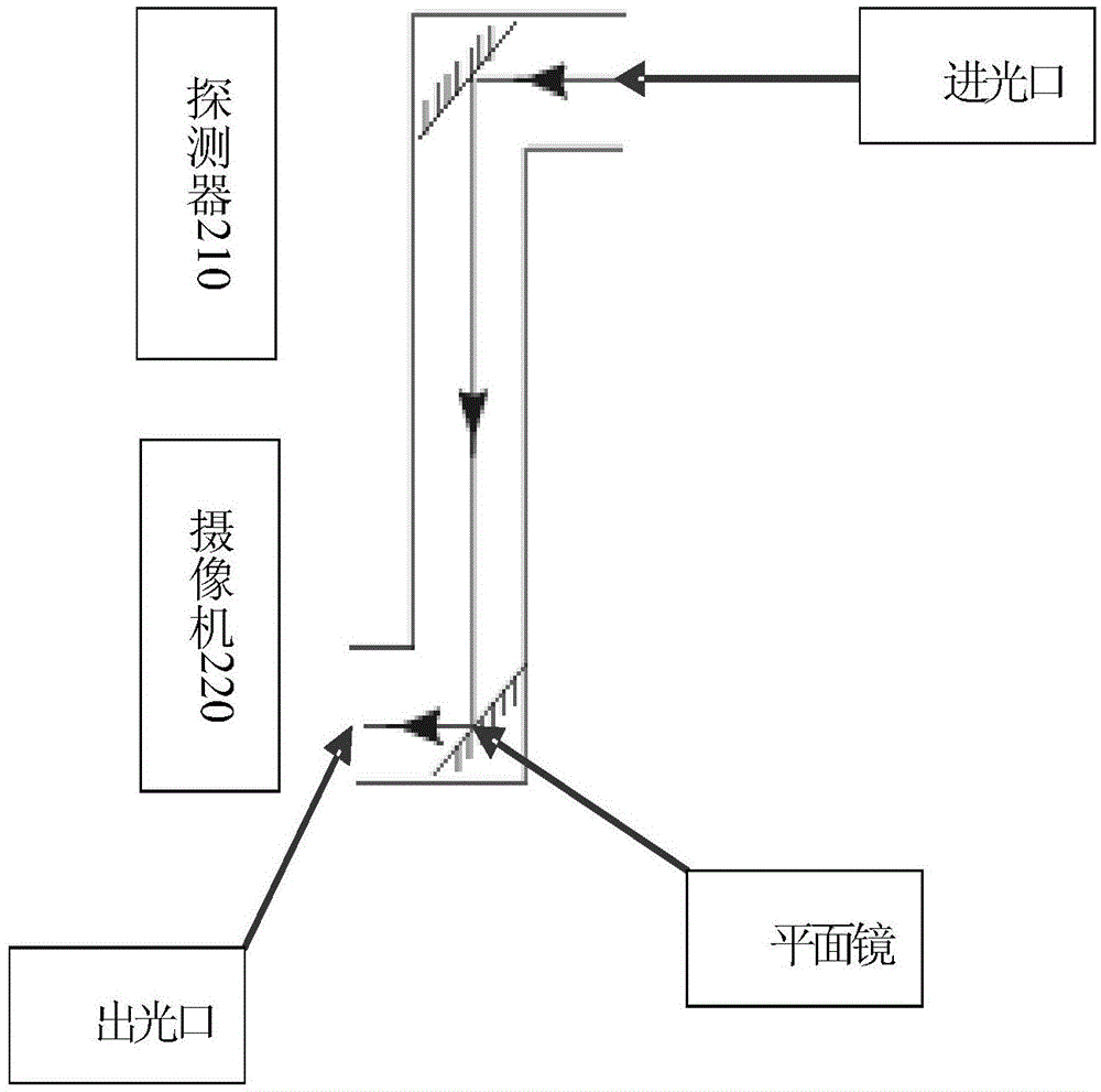
The invention provides a locator for monitoring a radioactive source. The locator comprises a detector used for detecting the radioactive source and generating a detector image of the radioactive source, a camera parallel and level to the detector in the vertical direction, and used for shooting a visible light image of the radioactive source, and a phase difference adjusting device used for adjusting a shooting region of the camera to enable the detector and a camera head of the camera to be in the same axial direction, so as to eliminate a phase difference between the radioactive source on the detector image and the radioactive source on the visible light image. By the adoption of the locator, the phase difference between the radioactive source on the detector image and the radioactive source on the visible light image can be eliminated. The invention further provides a method for monitoring the radioactive source.

Description

technical field [0001] The invention relates to the technical field of radioactive source monitoring, in particular to a locator for monitoring radioactive sources and a method for monitoring radioactive sources. Background technique [0002] In some radioactive material monitoring equipment, in order to calibrate the position of the radioactive source, the monitoring screen mainly consists of two parts: a detector image and a visible light image. The detector image is obtained by the detector using radiation detection technology, and the visible light image is obtained by the camera through video surveillance technology. However, in the monitoring screen, there is a certain deviation between the radioactive source position calibrated by radiation detection and the radioactive source position in the video surveillance screen. . Contents of the invention [0003] This application is based on the inventor's discovery of the following facts and problems: the inventor found t...

Claims


Application Information

Patent Timeline
Patent Type & Authority Applications(China)
IPC IPC(8): G01T7/00G01T1/00
Inventor 龚光华何峰张弥刘亚强王石刘迈
Owner BEIJING NOVEL MEDICAL EQUIP LTD
Learn More