Transformer bobbin

A transformer bobbin and coil bobbin technology, applied in the field of bobbins, can solve problems such as insufficient space for transformers

Active Publication Date: 2017-02-01
HEFEI PHILEX ELECTRONICS TECH
View PDF5 Cites 0 Cited by
  • Summary
  • Abstract
  • Description
  • Claims
  • Application Information

AI Technical Summary

Problems solved by technology

[0003] The technical problem to be solved by the present invention is to provide a transformer skeleton, which can effectively solve the problem of insufficient space in traditional transformers, and increase the number of coils in the effective space

Method used


Image

  • Transformer bobbin
  • Transformer bobbin
  • Transformer bobbin

Examples


Embodiment Construction

[0013] The present invention will be described in further detail below according to the drawings and embodiments.

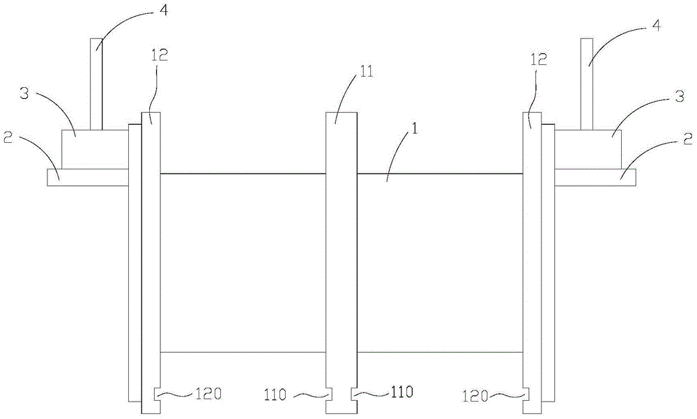
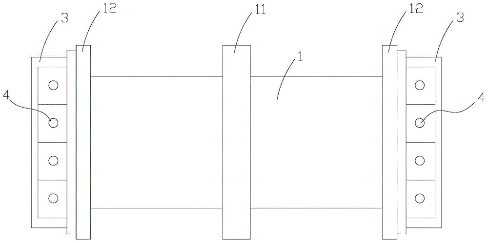
[0014] figure 1 It is a schematic diagram of the front view structure of the transformer skeleton in this implementation case, figure 2 For the top view structural diagram of the transformer skeleton in this implementation case, refer to figure 1 , figure 2 In the present invention, the transformer skeleton includes a rectangular coil frame 1, two end plates 2, a plurality of fixing blocks 3, a plurality of pins 4, and two protective shells. A rectangular retaining ring 11 that is separated and wider than the above-mentioned coil frame 1, and a fixed ring 12 that is rectangular and wider than the above-mentioned coil frame 1 is respectively fixed at both ends of the above-mentioned coil frame 1, and the two above-mentioned end plates 2 are respectively provided On the top of the outer surfaces of the two above-mentioned fixed rings 12, and the above-mentione...


PUM


Abstract

The invention discloses a transformer skeleton. The transformer skeleton comprises a rectangular coil rack, two end plates, a plurality of fixing blocks, a plurality of pins and two protective shells. The coil rack is transversely arranged, a rectangular check ring which divides a coil and is wider than the coil rack is arranged in the middle of the coil rack, and the two ends of the coil rack are respectively and fixedly connected with a rectangular fixing ring which is wider than the coil rack. The two end plates are arranged on the upper portions of the outer surfaces of the two fixing rings respectively, the end plates are horizontally arranged, and the two end plates are respectively provided with the fixing blocks. One pin is inserted in the upper surface of each fixing block. The bottoms of the inner surfaces of the fixing rings and the bottoms of the two faces of the check ring are respectively provided with a transverse sliding groove. Each protective shell comprises a base plate and two sub plates, and the two sub plates rotate upwards and are buckled on the top of the coil rack. The transformer skeleton has the advantages of being excellent in overall using effect and suitable for application and popularization.

Description

technical field [0001] The invention relates to a skeleton, especially a transformer skeleton. Background technique [0002] Traditional transformers, especially those with pins, have a simple structure and can be used in a wide range of fields. The skeleton of this type of traditional transformer has the following problems: the height of the transformer is limited, so that the number of coils wound on the coil frame is limited; at the same time, the existence of the outer protective shell of the traditional transformer makes the use of the internal space of the transformer limited. To a certain extent, the performance of the transformer is limited. Contents of the invention [0003] The technical problem to be solved by the present invention is to provide a transformer skeleton, which can effectively solve the problem of insufficient space in traditional transformers and increase the number of coils in the effective space. [0004] The present invention is achieved thro...

Claims


Application Information

Patent Timeline
Patent Type & Authority Patents(China)
IPC IPC(8): H01F27/30
Inventor 甘立豹汪洋范德军张孝虎何俊
Owner HEFEI PHILEX ELECTRONICS TECH
Why Eureka
Try Eureka