Ink ribbon cartridge

A technology for ink ribbon cassettes and ink ribbons, applied in the directions of ink ribbon cassettes, inking devices, printing, etc., can solve the problems of unreliable image printing media, etc., and achieve the effect of preventing contact and increasing the number of windings

Inactive Publication Date: 2010-10-27
SONY CORP
View PDF7 Cites 0 Cited by
  • Summary
  • Abstract
  • Description
  • Claims
  • Application Information

AI Technical Summary

Problems solved by technology

Therefore, if the size of the take-up-side tape accommodating portion becomes large, the position of the flap positioned at the take-up-side tape accommodating portion changes, so that the image printing medium cannot be reliably run, and thus it becomes impossible to accommodate the take-up-side tape accommodating portion. Partially for use with existing thermal transfer printer units

Method used


Image

  • Ink ribbon cartridge
  • Ink ribbon cartridge
  • Ink ribbon cartridge

Examples


Embodiment Construction

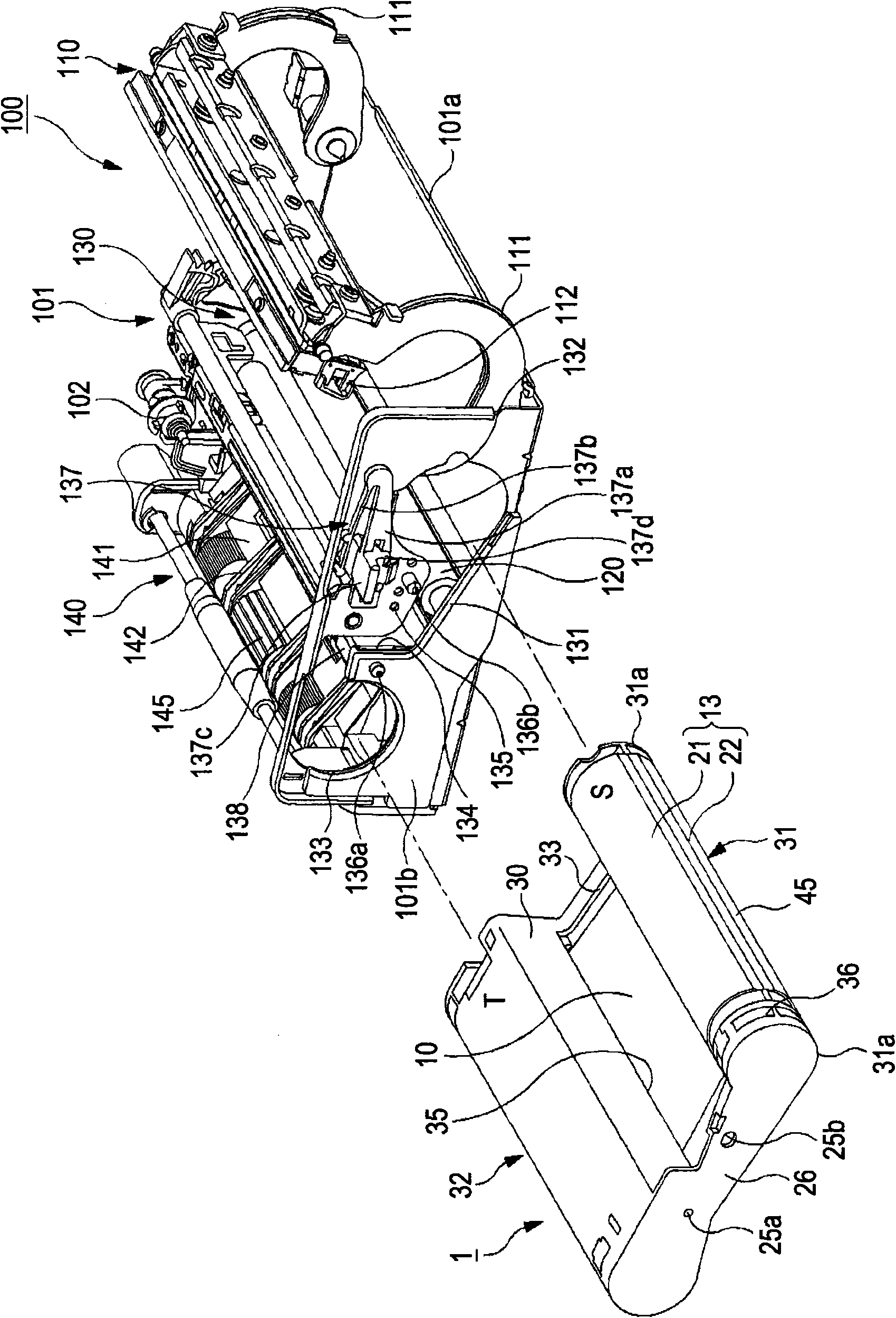
[0034] An ink ribbon cartridge according to an embodiment of the present invention will be described in the following order with reference to the drawings.

[0035] 1. General description

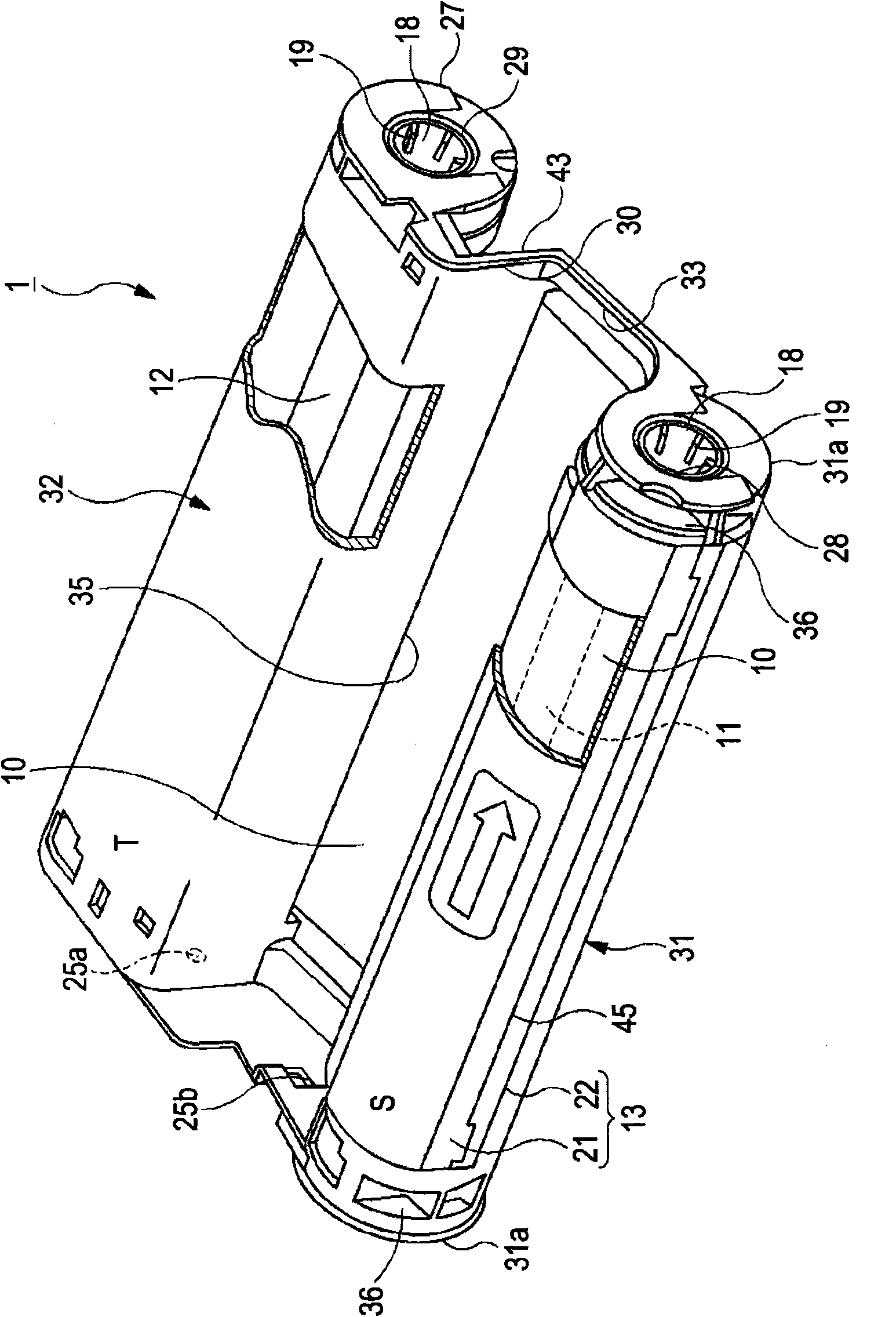
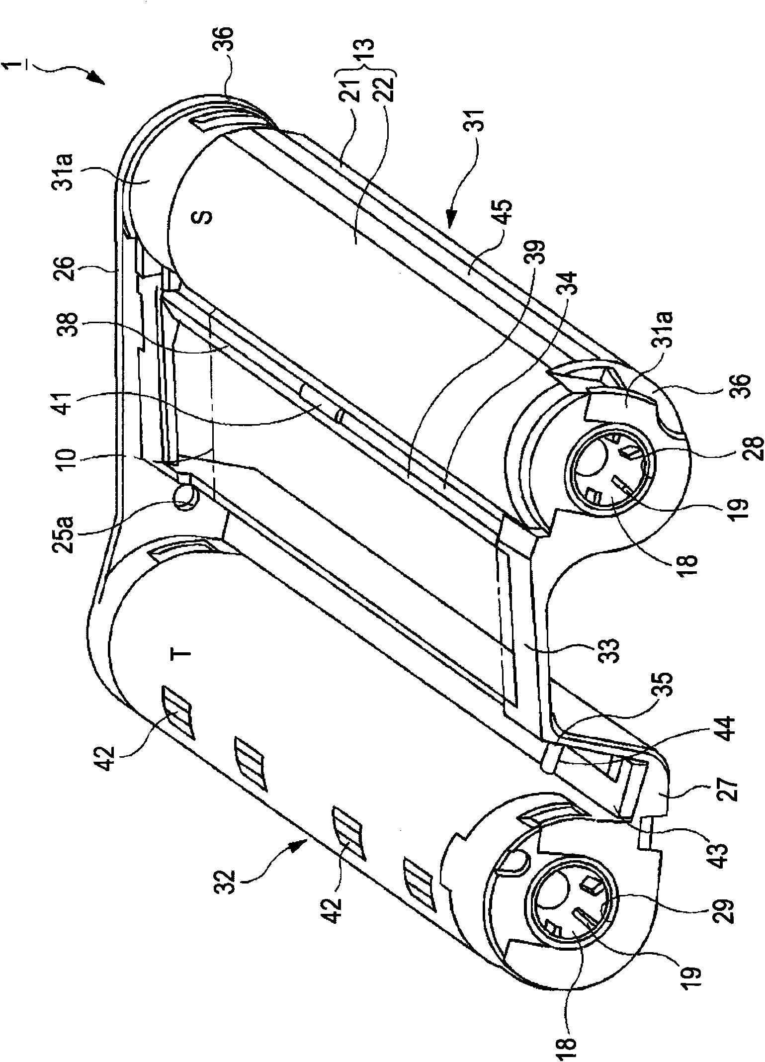
[0036] 2. Description of ink ribbon box

[0037] 2-1. Ink Ribbon Description

[0038] 2-2. Description of the scroll

[0039] 2-3. Description of the box body

[0040] 2-4. Explanation of supply side belt housing

[0041] 2-5. Explanation of belt guide

[0042] 2-6. Description of concave guide

[0043] 2-7. Explanation of the take-up side belt housing

[0044] 2-8. Explanation of supply side flat part and winding side flat part

[0045] 3. Description of thermal transfer printer unit

[0046] 3-1. Explanation of box installation part

[0047] 3-2. Description of thermal head and drum

[0048] 3-3. Description of the transport mechanism of the image printing medium 150

[0049] 4. Operating Instructions

[0050] 5. Effect description

[0051] 5-1. Effect 1

[0052] 5-2. Effect 2...


PUM


Abstract

An ink ribbon cartridge includes: a supply spool, on which an ink ribbon is wound; a winding spool which takes up the ink ribbon sent from the supply spool; and a cartridge main body which has a supply-side ribbon housing section which houses the supply spool so as to be able to rotate, and a winding-side ribbon housing section which houses the winding spool so as to be able to rotate, and in which a head entry opening portion, into which a thermal head enters, is formed between the supply-side ribbon housing section and the winding-side ribbon housing section, and opening portions for the ribbon, which make the ink ribbon extend in the head entry opening portion, are formed on the head entry opening portion side of the supply-side ribbon housing section and the head entry opening portion side of the winding-side ribbon housing section.

Description

technical field [0001] The present invention relates to an ink ribbon cartridge for a printer device in which a cartridge body accommodating an ink ribbon is installed and pigments of the ink ribbon are transferred to an image printing medium through a thermal head. More specifically, the present invention relates to an ink ribbon cassette capable of winding a large amount of ink ribbon. Background technique [0002] As a printer device that prints images or characters on an image printing medium, there is a printer device that prints a color image or characters by transferring a pigment forming an ink layer provided on one side of an ink ribbon to the image printing medium. This printer device is provided with a thermal head that transfers a colorant of an ink ribbon to an image printing medium, and a roller that is disposed at a position opposite to the thermal head and supports the ink ribbon and the image printing medium. The printer device transfers the pigment of the ...

Claims


Application Information

Patent Timeline
Patent Type & Authority Applications(China)
IPC IPC(8): B41J32/00
CPCB41J35/28B41J17/32
Inventor 小山升村田和庆一瀬新吾
Owner SONY CORP
Why Eureka
Try Eureka