
Method and system for monitoring moving objects

A technology of moving objects and sensors, applied in electrical components, wireless communication, network topology, etc., can solve the problems of difficult installation and maintenance of sensors, failure to provide satisfactory equipment, etc., and achieve the effect of enhancing security and preventing tampering

Active Publication Date: 2018-06-19
CHINA UNITED NETWORK COMM GRP CO LTD
View PDF1 Cites 0 Cited by
  • Summary
  • Abstract
  • Description
  • Claims
  • Application Information

AI Technical Summary

Problems solved by technology

[0004] However, when it is necessary to monitor in some harsh environments and inaccessible areas for scientific research or military purposes, the current monitoring solution through video data will have major defects. On the one hand, due to the large amount of video data, Whether it is on-site processing or transmission, equipment with high performance is required, and equipment that meets this demand is often not available in harsh environments. On the other hand, the installation and maintenance of sensors are also difficult

Method used


Image

  • Method and system for monitoring moving objects
  • Method and system for monitoring moving objects
  • Method and system for monitoring moving objects

Examples


Embodiment 1

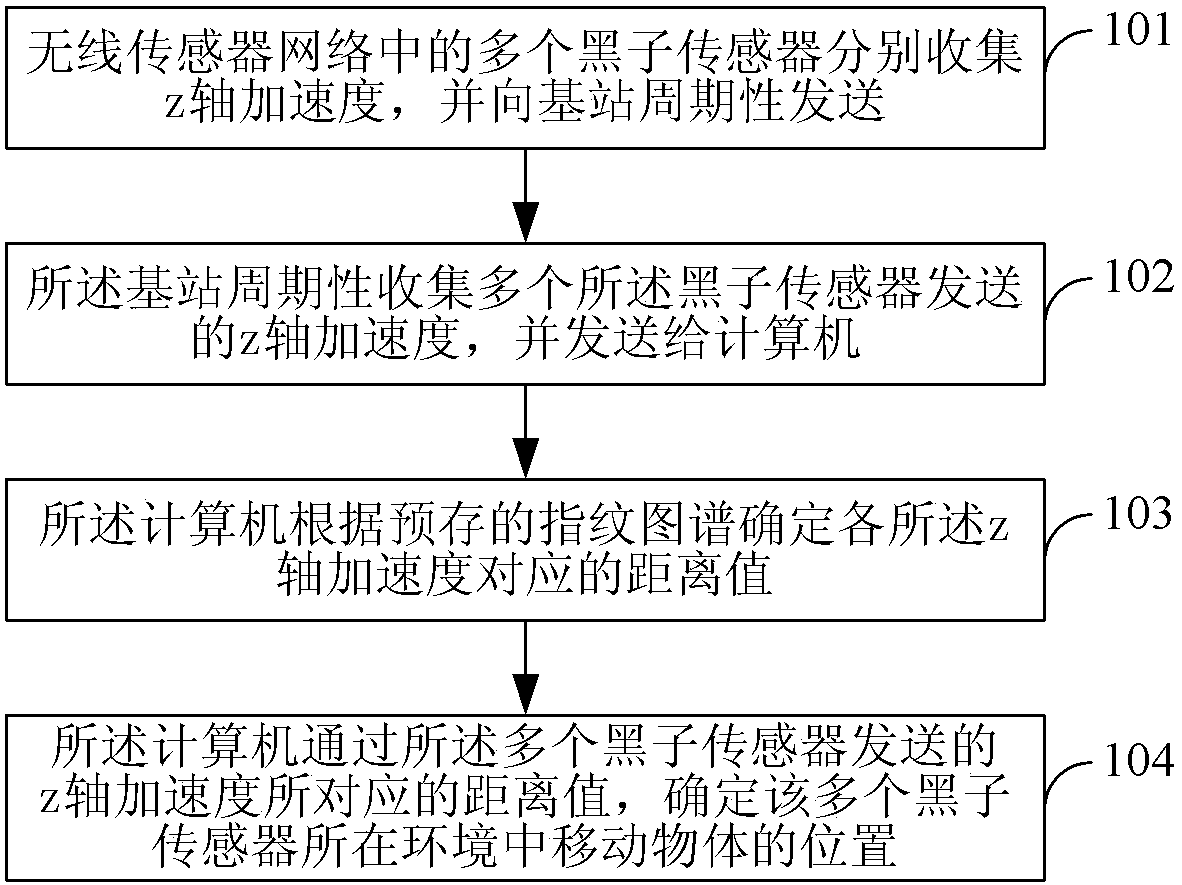
[0053] Embodiment 1. A mobile object monitoring method, such asfigure 1 shown, including:

[0054] 101. Multiple sunspot sensors in the wireless sensor network respectively collect the standard deviation of the z-axis acceleration, and periodically send it to the base station;

[0055] 102. The base station periodically collects a plurality of z-axis acceleration standard deviations sent by the sunspot sensors, and sends them to the computer;

[0056] 103. The computer determines the distance value corresponding to each z-axis acceleration standard deviation according to the pre-stored fingerprint;

[0057] 104. The computer determines the position of the moving object in the environment where the multiple sunspot sensors are located through the distance value corresponding to the standard deviation of the z-axis acceleration sent by the multiple sunspot sensors.

[0058] A wireless sensor network is composed of spatially distributed autonomous sensors (nodes) in a self-organ...

Embodiment 2

[0137] Embodiment 2. A mobile object monitoring system, comprising:

[0138] A plurality of sunspot sensors, a base station and computing; the plurality of sunspot sensors and the base station are connected through a wireless sensor network;

[0139] The sunspot sensor is used to collect the standard deviation of the z-axis acceleration and periodically send it to the base station;

[0140]The base station is used to periodically collect the z-axis acceleration standard deviation sent by the plurality of sunspot sensors, and send it to the computer;

[0141] The computer is used to determine the distance value corresponding to each z-axis acceleration standard deviation according to the pre-stored fingerprint; through the distance value corresponding to the z-axis acceleration standard deviation sent by the plurality of sunspot sensors, determine the plurality of sunspot sensors The position of a moving object in its environment.

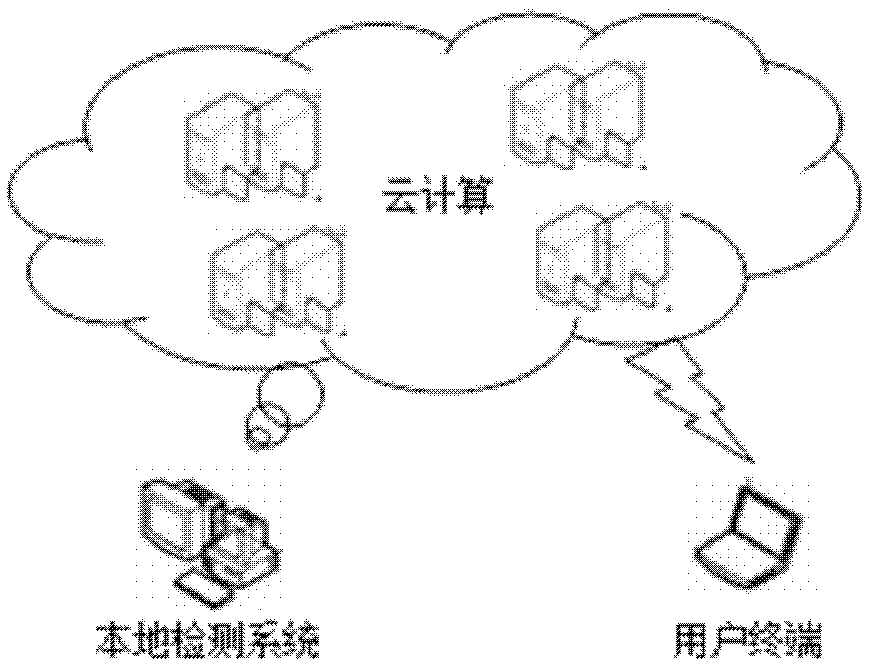
[0142] The computer may be a local computer...


PUM


Abstract

The invention provides a method and a system for monitoring a moving object. The method comprises the following steps: 101, z-axis accelerations are respectively collected by a plurality of sunspot sensors in a wireless sensor network and are periodically transmitted to a base station; 102, the z-axis accelerations respectively collected by the sunspot sensors are periodically collected by the base station and are transmitted to a computer; 103, the computer determines a distance value corresponding to each z-axis acceleration according to a pre-stored fingerprint; and 104, the computer determines a position of the moving object in the environment, in which the sunspot sensors are positioned, through the distance values corresponding to the z-axis accelerations transmitted by the sunspot sensors. The method and the system can adopt lightweight data to complete monitoring of the moving object and have the advantages of high reliability and easy implementation.

Description

technical field [0001] The invention relates to the field of monitoring, in particular to a method and system for monitoring a moving object. Background technique [0002] As the basis of video surveillance technology, mobile monitoring and tracking technology has become a hot research topic in recent decades. This technology can be widely used in various fields. For example, surveillance systems can use detection and tracking technology to monitor object movement. Augmented by video tracking, the system can be used to monitor road traffic and track objects. [0003] In general, most current monitoring and tracking systems for moving objects utilize wireless sensors deployed in the test field to collect environmental data in advance. The sensor will choose to feed back video data to the central base station or share information with one or several sensors in it, so as to detect the uncertain path of the moving body in the test field. Through the combination of the monito...

Claims


Application Information

Patent Timeline
Patent Type & Authority Patents(China)
IPC IPC(8): H04W12/04H04W12/06H04W84/18
Inventor 李丹张云勇魏进武张基恒
Owner CHINA UNITED NETWORK COMM GRP CO LTD
Learn More