Hybrid system control device

A technology of hybrid power system and control device, which is applied in the direction of power devices, hybrid vehicles, air pressure power devices, etc., can solve the problem of being unable to restrain the impact, and achieve the effect of restraining the impact

Active Publication Date: 2014-11-19
TOYOTA JIDOSHA KK
View PDF8 Cites 2 Cited by
  • Summary
  • Abstract
  • Description
  • Claims
  • Application Information

AI Technical Summary

Problems solved by technology

Therefore, in this case, since the direction of the reaction force generated on the output shaft does not change, although the shock generated on the output shaft can be reduced, there is a possibility that the generation of the shock cannot be suppressed.

Method used


Image

  • Hybrid system control device
  • Hybrid system control device
  • Hybrid system control device

Examples


Embodiment

[0055] based on Figure 1 to Figure 38 An embodiment of a control device for a hybrid system according to the present invention will be described.

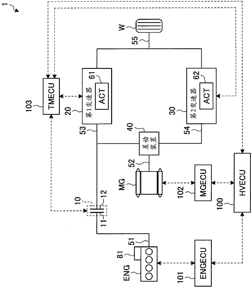
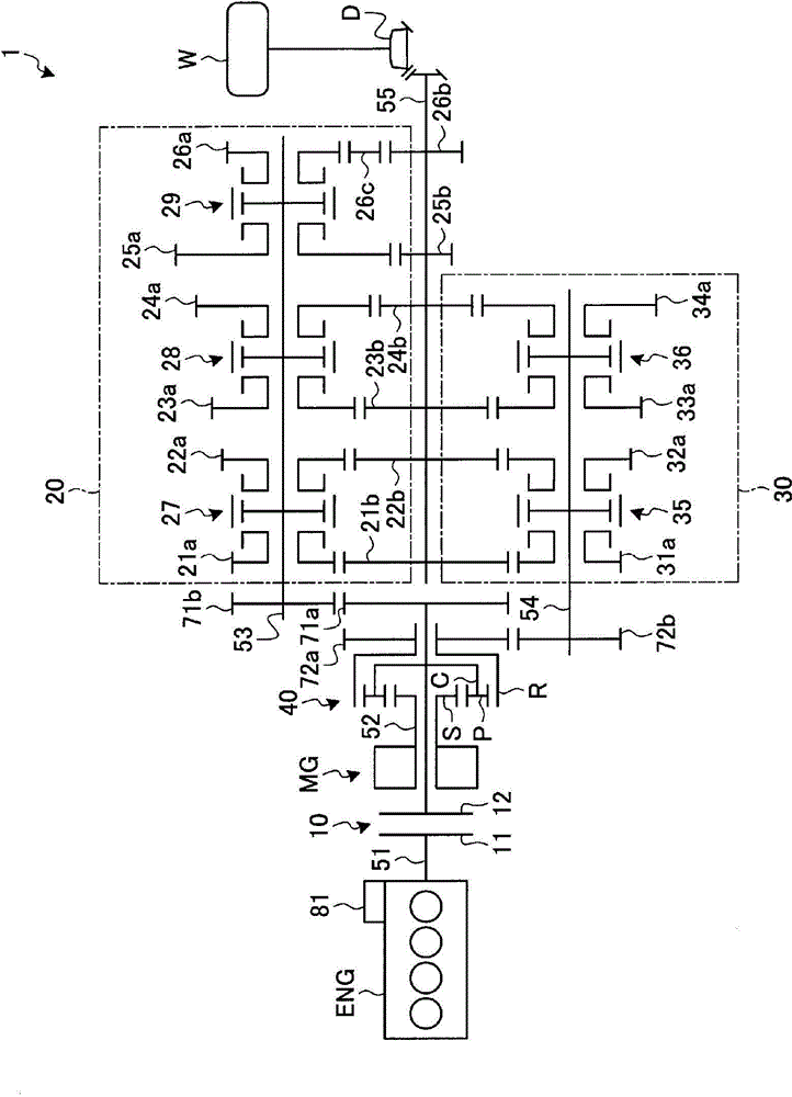
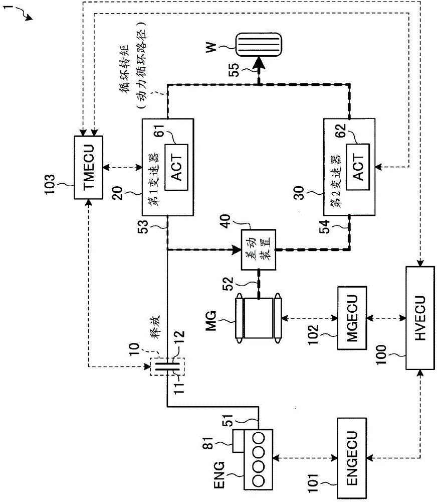
[0056] figure 1 and figure 2 Symbol 1 in represents the hybrid system of this embodiment. figure 1 The structure of the hybrid system 1 of this embodiment is shown simply. figure 2 A specific example of the hybrid system 1 of this embodiment is shown.

[0057] This hybrid system 1 includes an engine ENG, a motor / generator MG, an automatic clutch 10 , a first transmission 20 , a second transmission 30 , and a differential device 40 .

[0058] The engine ENG is a mechanical power source such as an internal combustion engine or an external combustion engine that outputs mechanical power (engine torque) from an engine rotating shaft (crankshaft) 51 . The operation of the engine ENG is controlled by an electronic control unit (hereinafter referred to as “engine ECU (ENGECU)”) 101 for engine control. In addition, the motor / gener...


PUM


Abstract

A hybrid system control device comprises: an engine (ENG); a motor / generator (MG); an automatic clutch (10) in which an engine rotation axle (51) is connected to a first engagement part (11) side thereof; a differential device (40) further comprising a plurality of rotation elements in which an MG rotation axle (52) and a second engagement part (12) side of the automatic clutch (10) are respectively independently connected; a first transmission (20) in which a rotation axle (53) is connected to the same rotation element as the second engagement part (12) side; a second transmission (30) in which a rotation axle (54) is connected to another rotation element; and an output axle (55) which is connected to a drive wheel (W) side. When in EV travel, the first transmission and the second transmission are controlled and the automatic clutch is disengaged such that torque may be transmitted among the I / O axles of the respective first and second transmissions. When starting the engine during EV travel, the engine RPM is increased by engaging the automatic clutch during EV travel, and the amount of reduction of the drive torque which is reduced commensurate with the engagement of the automatic clutch is compensated for by output torque of the motor / generator.

Description

technical field [0001] The present invention relates to an automatic clutch having an engine, an electric motor / generator, one coupling part side connected to the engine rotation shaft, and a plurality of coupling parts independently connected to the rotation shaft of the motor / generator and the other coupling part side of the automatic clutch. A differential device of a rotating member, a first transmission having at least one gear stage connected to the rotating member of the differential device on the same side as the other engaging portion of the automatic clutch, and a first transmission having other rotating members connected to the differential device A control device for a hybrid system of a second transmission with at least one gear stage. Background technique [0002] For example, such a hybrid system is disclosed in the following patent documents 1-3. In the hybrid system of Patent Document 1, five shift speeds and reverse gears are arranged as the first transmis...

Claims


Application Information

Patent Timeline
Patent Type & Authority Applications(China)
IPC IPC(8): B60W20/00B60K6/365B60K6/48B60W10/02B60W10/08
CPCB60W20/40B60W10/08B60W10/06Y02T10/6221B60W10/02B60W2710/021B60K6/365B60K6/48B60W20/00Y02T10/62B60W10/113Y10S903/93B60K2006/268B60K6/36B60K6/38B60W10/10B60W20/10
Inventor 矶村治郎江渕弘章柴田宽之
Owner TOYOTA JIDOSHA KK
Why Eureka
Try Eureka