
valves for fluid control

A technology for fluid and control sections, applied in the direction of sliding valves, valve details, valve devices, etc., can solve problems affecting flow characteristics, etc., and achieve high stability and good visibility

Active Publication Date: 2016-05-25
FESTO AG & CO KG
View PDF11 Cites 0 Cited by
  • Summary
  • Abstract
  • Description
  • Claims
  • Application Information

AI Technical Summary

Problems solved by technology

A disadvantage of such multi-way valves with a rotatable valve element is, inter alia, that the fluid passing through the valve element in the open position experiences deflections which affect the flow behavior.

Method used


Image

  • valves for fluid control
  • valves for fluid control
  • valves for fluid control

Examples


Embodiment Construction

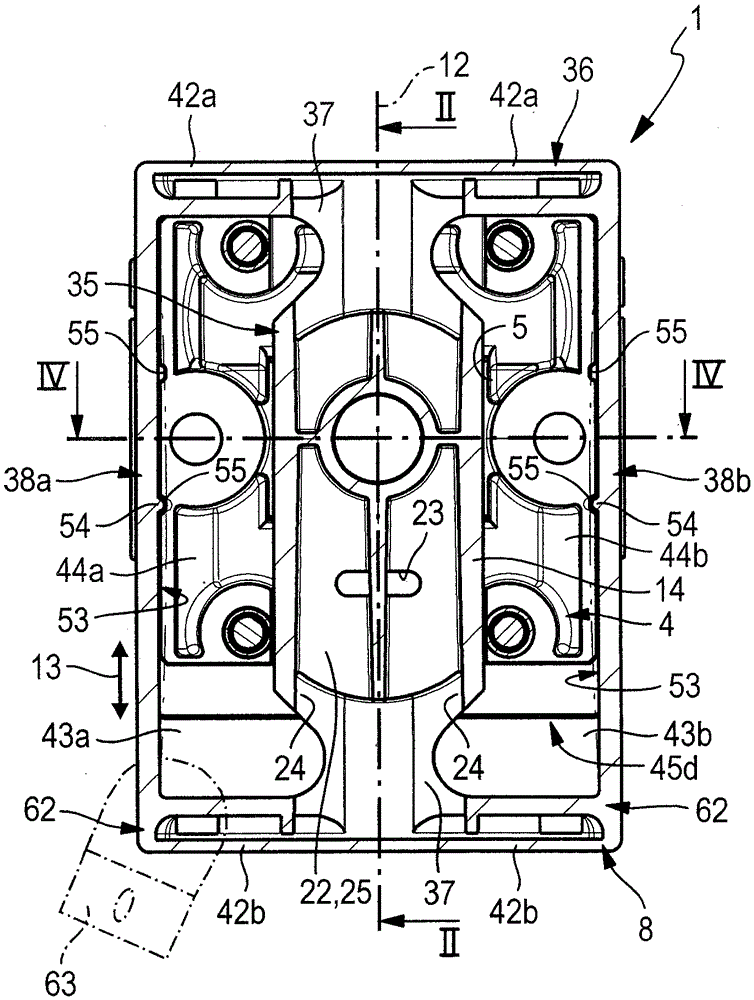
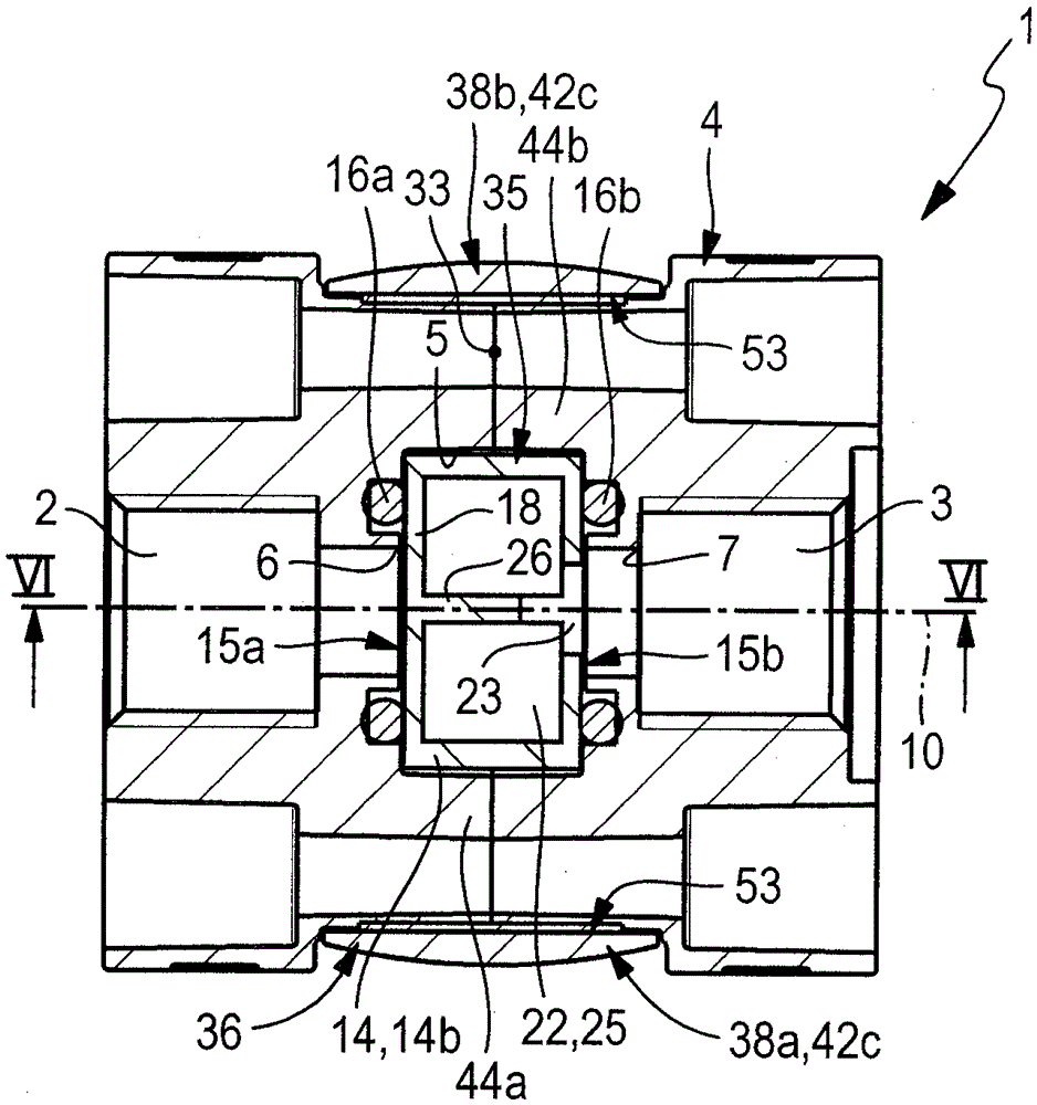
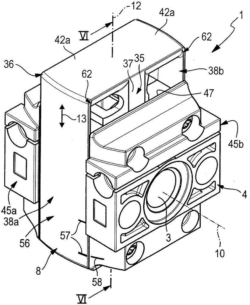
[0037] The valve, designated as a whole by reference number 1 , serves to control the flow of fluid between the first fluid channel 2 and the second fluid channel 3 . Although the valve 1 can be used to control any flowable medium, the fluid to be controlled is especially compressed air.

[0038] The valve 1 comprises a valve housing 4 which delimits a preferably approximately slit-shaped valve chamber 5 into which the two fluid channels 2 , 3 open with first and second channel openings 6 , 7 lying opposite each other in the main direction 10 . In the valve chamber 5. The two fluid channels 2 , 3 pass through the valve housing 4 and each lead out to the outer surface of the valve housing 4 with a connection opening 2 a , 3 a. Preferably, the two fluid channels 2 , 3 extend coaxially to one another, wherein the orientation of their longitudinal axes coincides with the main direction 10 .

[0039] In a preferred mode of operation of the valve 1 , the first fluid channel 2 is u...


PUM


Abstract

The invention relates to a valve (1) suitable for fluid control, comprising a valve housing (4) and a valve slide (8) that is movable relative to the valve housing (4). The valve slide (8) contains a control section (14) that controls the connection between two fluid channels and at least one U-shaped handling bracket (38a, 38b) that is arranged on the control section (14), partially surrounds the valve housing (4) externally, and can be actuated manually for switching of the valve (1).

Description

technical field [0001] The invention relates to a valve for fluid control with a valve housing delimiting a valve chamber in which two passage openings of two fluid passages lie opposite each other at a distance in the main direction and In the valve chamber, the control section (Stuerabschnitt) of the valve slide (Ventilschieber) extends between these two channel openings, the valve slide can be adjusted for different operating positions in an adjustment direction perpendicular to the main direction relative to the valve housing The housing moves linearly to and fro, wherein a respective drive section available for introducing a displacement force is coupled axially on both sides in the adjustment direction to the control section of the valve slide. Background technique [0002] A valve of this type known from EP0052703B1 is designed as a plate slide and can be actuated by means of fluid forces. It comprises a valve housing in which a valve slide is arranged linearly displ...

Claims


Application Information

Patent Timeline
Patent Type & Authority Patents(China)
IPC IPC(8): F16K3/02F16K27/04
CPCF16K3/0254F16K27/044
Inventor R.雅赫曼J.佩舍尔
Owner FESTO AG & CO KG
Learn More