Building block type dummy body structure of punching bag

A technology of building blocks and piles, which is applied in the field of building block pile structures, can solve the problems of unfavorable packaging, storage and transportation, redundant piles, high storage and transportation costs, and achieve the effect of saving transportation costs and facilitating storage and storage

Active Publication Date: 2014-11-26
苏州搏克形健身器材有限公司
View PDF10 Cites 7 Cited by
  • Summary
  • Abstract
  • Description
  • Claims
  • Application Information

AI Technical Summary

Problems solved by technology

[0003] Not limited to the patents and patent application schemes listed above, although each has corresponding technical effects, there are disadvantages that are not conducive to packaging, storage and transportation. Specifically, due to the lengthy and heavy piles, the requirements for packaging are relatively high. Strict, high storage and transportation costs, especially when exporting to foreign countries, there is an embarrassing situation where the transportation cost and the pile body cost go hand in hand or even put the cart before the horse
This problem has plagued boxing sandbag manufacturers for a long time, and so far there is no effective countermeasure

Method used


Image

  • Building block type dummy body structure of punching bag
  • Building block type dummy body structure of punching bag
  • Building block type dummy body structure of punching bag

Examples


Embodiment 1

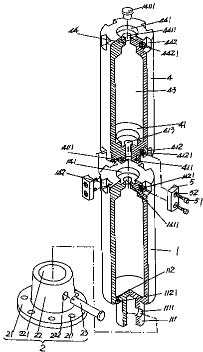
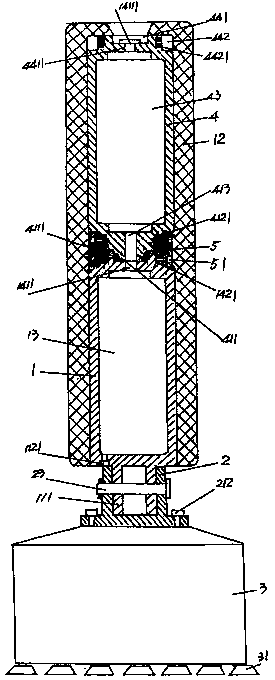
[0021] See figure 1 and figure 2 , shows a pile body 1 made of plastic, in the use state of the bottom wall 11 of the pile body 1, there extends toward the middle position of the lower side with a diameter smaller than the diameter of the pile body 1 and connected to the bottom The wall 11 forms a base joint 111 in a vertical relationship, and a striking layer 12 is integrated on the outer wall of the pile body 1 and around the periphery of the pile body 1 .

[0022] As the technical points of the technical solution of the present invention: the aforementioned pile body 1 forms a pile body cavity 13, on the top wall 14 of the pile body 1 and at the center of the side of the top wall 14 facing away from the pile body cavity 13 The position constitutes an additional pile body connection seat standby cavity 141 depressed on the surface of the top wall 14, and a central position at the bottom of the additional pile body connection seat standby cavity 141 is provided with a pile ...

Embodiment 2

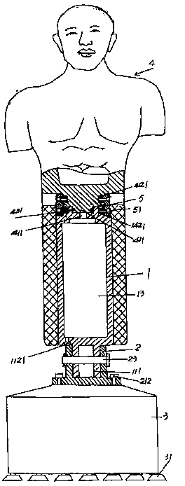
[0035] See image 3 , just change the shape of the first-level additional pile body 4 into the shape of the mannequin (other similar shapes can also be arranged), and all the other are the same as the description of embodiment 1.

Embodiment 3

[0037] See Figure 4 Add a second-level additional pile body 6 that is identical in structure to the first-level additional pile body 4 on the top of the first-level additional pile body 4, and change the base 3 into a plate-shaped structure, and the pile body 1, The height of the first-level additional pile 4 and the height of the second-level additional pile 6 is selected as 0.5m, and the connection between the second-level additional pile 6 and the first-level additional pile 4 is the same as the connection between the first-level additional pile 4 and the pile body 1. Description of the connection, and the striking layer 12 extends to the outer wall of the secondary additional pile body 6, the opening and closing cover 4111 of the medium introduction hole is transferred to the top of the secondary additional pile body 5, and the rest of the content not mentioned is the same as that of embodiment 1 description of.


PUM


Abstract

The invention relates to a building block type dummy body structure of a punching bag and belongs to the technical field of sports equipment. The structure comprises a dummy main body, a base connector is arranged on one side of the bottom wall in an extending mode, and a beating layer is arranged on the outer wall. The building block type dummy body structure is characterized in that a dummy main body cavity is formed in the dummy main body, an additional dummy body connecting base standby cavity is formed in the top wall of the dummy main body, a medium leading-in hole is formed in the bottom of the cavity, and a set of additional dummy body fixing cavities is formed in the side faces of the top wall. Additional dummy body connecting nuts are arranged in the additional dummy body fixing cavities, and a medium leading-out hole is formed in the bottom wall. A medium leading-out hole opening and closing cover is arranged on the medium leading-out hole, and a first-stage additional dummy body is arranged at the top of the dummy main body. A second-stage additional dummy body connecting base standby cavity is formed in the center of one side, backing on to a first-stage additional dummy body cavity, of the top wall of the first-stage additional dummy body, and the outer wall of the first-stage additional dummy body is covered with the beating layer in an extending mode. The dummy body structure is light, the packing requirement can be lowered, collecting and storing are convenient, and the transportation cost is reduced.

Description

technical field [0001] The invention belongs to the technical field of sports equipment, and in particular relates to a building block pile structure of a boxing sandbag. Background technique [0002] Boxing sandbags include wooden dummy sandbags. Wooden dummy sandbags are also called tumbler sandbags. They are usually composed of a base and a pile body, and there is no shortage of technical information about wooden dummy sandbags in published Chinese patent documents, such as the recommendation of CN201214007Y "A three-in-one foot target with a suction cup base tumbler, a sandbag, and a wooden dummy", CN2452560Y provided "a non-falling sandbag", CN2346472Y introduced a "boxing sandbag", CN201701714U disclosed a "wooden dummy sandbag", CN102357298A The "stacked sandbag" disclosed and the "wooden pile sandbag" recommended by CN102397690A, etc. [0003] Not limited to the patents and patent application schemes listed above, although each has corresponding technical effects, ...

Claims


Application Information

Patent Timeline
Patent Type & Authority Applications(China)
IPC IPC(8): A63B69/22
Inventor 顾元龙
Owner 苏州搏克形健身器材有限公司
Why Eureka
Try Eureka