
Support mechanism of movable object

A technology of moving body and active connecting rod, applied in the field of supporting mechanism, can solve problems such as excess propulsion force, inability to accurately locate, and difficulty in accurately positioning

Active Publication Date: 2014-11-26
HUIZHOU SAGETECH OPTRONICS CO LTD
View PDF7 Cites 3 Cited by
  • Summary
  • Abstract
  • Description
  • Claims
  • Application Information

AI Technical Summary

Problems solved by technology

However, the frictional force will be reduced during the movement, but maintaining the energization at the beginning of the movement will lead to excess propulsion force, causing the lens holder 402 to easily exceed the predetermined stop position and overrun, making it difficult to accurately position.
[0018] As described above, the hand-shake correction device 310 of the wire suspension system in which the lens driving device 300 is supported by the suspension wire 302 has a problem that it is easy to rotate around an axis parallel to the optical axis.
In addition, the lens driving device 300 of the leaf spring suspension system can move the lens holder 307 smoothly, but there is a problem that the lens holder 307 is inclined to be easily tilted relative to the optical axis due to the phenomenon of inclination.
Furthermore, in the lens driving device 400 of the shaft sliding method, the lens holder 402 is not likely to be tilted, but it is difficult to move the lens holder 402 smoothly, resulting in the problem of inaccurate positioning.

Method used


Image

  • Support mechanism of movable object
  • Support mechanism of movable object
  • Support mechanism of movable object

Examples


Embodiment Construction

[0042] Hereinafter, the present invention will be described in detail through the embodiments, but the following embodiments do not limit the invention described in the claims, and do not limit all combinations of features described in the embodiments to be essential to the solution means of the invention.

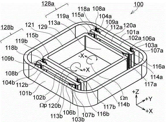
[0043] figure 1 It is a perspective view which shows the support mechanism of 1st Embodiment of this invention. The support mechanism 100 includes: +Y side compound link 128a; -Y side compound link 128b; a square frame-shaped fixed frame 129 opening in the Z-axis direction; A square frame-shaped movable body connecting member 121 . The fixed frame 129 is connected to an unillustrated fixed base, and the movable body connecting member 121 is connected to an unillustrated movable body. The body moves in a direction at right angles to the Z axis.

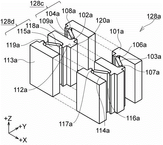
[0044] figure 2 It is a perspective view of the +Y side compound link 128a. Hereinafter, since the +Y side compound link 1...


PUM


Abstract

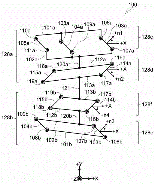
The invention discloses a support mechanism which doesn't cause rotation and can smoothly and accurately perform moving the support mechanism of the movable body in parallel. The outer side fixing rod (101a) +Y composite connection rod (128a) formed by connecting the outer side parallel connection rod (128c) and the inner side connection rod in parallel is connected to the fixing frame (129);the outer side fixing connection rod (101b) of the -Y side composite connection rod (128b) formed by connecting the outer side parallel connection rod (128e) and the inner side parallel connection rod (128f) in series is connected to the fixing frame; the inner side outputting connection rod (113a) of the +Y side composite connection rod (128a) is connected to the movable object connection member (121); and the inner side output connection rod (113b) of the-Y side composite connection rod (128b) is connected to the movable connection member (121) from the -Y side.

Description

technical field [0001] The present invention relates to a support mechanism of a movable body, in particular to a support mechanism of a camera lens and a lens driving device which need to move accurately and stably. Background technique [0002] In recent years, various functions are attached to mobile phones, and in particular, camera-equipped mobile phones equipped with a camera are widely used. Cameras installed in mobile phones have autofocus functions, and in addition to autofocus functions, camera shake correction functions are being upgraded and added. [0003] The hand shake correction device 310 shown in FIG. 14( a ) and ( b ) is one example. The hand-shake correction device 310 adopts a wire suspension method, so that the lens driving device 300 with an auto-focus function is swingably assembled in the camera. That is, the hand shake correction device 310 achieves focusing by moving the lens 305 along the optical axis direction (the O-axis direction), and moves ...

Claims


Application Information

Patent Timeline
Patent Type & Authority Applications(China)
IPC IPC(8): G03B5/00G02B7/04
CPCG02B7/08G02B27/646
Inventor 寺嶋厚吉
Owner HUIZHOU SAGETECH OPTRONICS CO LTD
Learn More