Reversing motor

A technology of a motor and a cover, applied in the field of motors, can solve the problems of waste of motor power and easy heating of the motor, and achieve the effects of enhanced thrust, less heat generation, and increased work efficiency

Inactive Publication Date: 2014-11-26
莫春浩 +1
View PDF6 Cites 0 Cited by
  • Summary
  • Abstract
  • Description
  • Claims
  • Application Information

AI Technical Summary

Problems solved by technology

[0006] The purpose of the present invention is to provide a bidirectional motor to solve the problems of motor power waste and motor heating in the prior art

Method used


Image

  • Reversing motor
  • Reversing motor
  • Reversing motor

Examples


Embodiment Construction

[0035] The bidirectional motor of the present invention is described below in conjunction with accompanying drawing and embodiment:

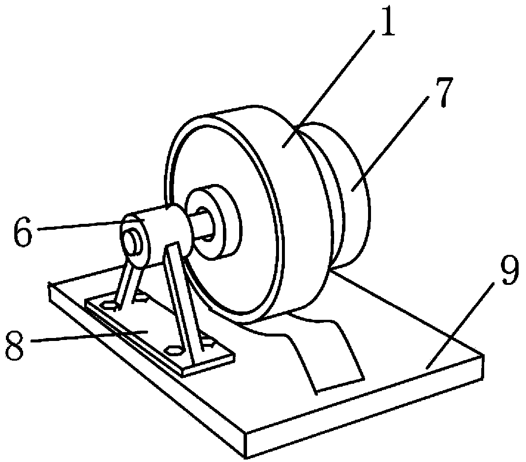
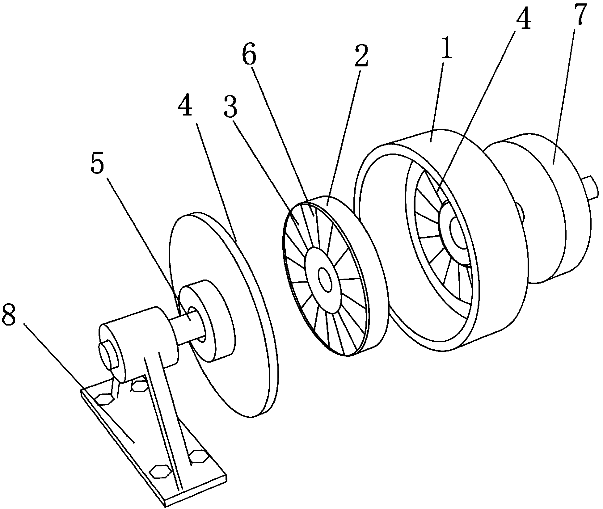
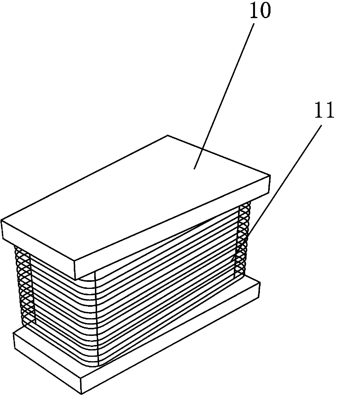
[0036] Such as Figure 1-3 As shown, the two-way motor in the present invention, the motor cover 1 and the coil support 2, the power shaft 5 is fixed on both sides of the coil support 2, and the coil support 2 is matched and installed in the bearing of the motor cover 1 through the power shaft 5. In this embodiment Among them, the coil support 2 is provided with 6 through-slots 3, and the through-slots 3 are circularly distributed in the center of the coil support 2, and the number of the through-slots 3 is an odd number. In this embodiment, there are seven through-slots 3. The slot 3 is inlaid with a wire core 10 in the shape of "I", and the wire core 10 is trapezoidal; the wire core 10 is wound with a coil 11, and the side cover of the motor cover 1 is provided with a magnet 4, and the number of the magnet 4 is the same as that of the slot. 3...


PUM


Abstract

The invention discloses a reversing motor. The reversing motor comprises a coil support and a motor cover and is characterized in that power shafts are fixed to the two sides of the coil support, and the coil support is installed in the motor cover in a matched mode through the power shafts; the coil support is provided with a plurality of through grooves which are annularly distributed around the center of the coil support; coil cores are arranged in the through grooves, coils are wound around the coil cores, and magnets are arranged at the side portion of the motor cover and closely attached to the coil cores and are different from the coil cores in number but the same as the coil cores in shape; the direction of magnetic force lines of the magnets are parallel with the direction of the coil cores.

Description

technical field [0001] The present invention relates to electric motors, in particular to a bidirectional electric motor. Background technique [0002] There are permanent magnets installed on the rotor or stator of the existing AC and DC motors seen at present. The opposite of the permanent magnets is the rotor or the stator. They are all provided with pits, and conductive coils are embedded in the pits. A pair of north and south magnetic poles can be generated in each coil at the same time, but in the work, only one magnetic pole does work, and the other magnetic pole is turned into a magnetic circuit iron plate by the outer round iron of the central axis of the rotor to short-circuit with other opposite magnetic poles. The closure disappears or the peripheral round iron frame of the stator becomes the magnetic circuit iron plate with the same polarity to cause the short circuit closure to disappear. In fact, nearly half of the power of the traditional AC and DC permanent...

Claims


Application Information

Patent Timeline
Patent Type & Authority Applications(China)
IPC IPC(8): H02K21/24
Inventor 丁冠东莫春浩莫长成莫长健莫长创
Owner 莫春浩
Why Eureka
Try Eureka