
Drilling jig for pump body of clutch master cylinder

A clutch master cylinder and drilling jig technology, applied in the direction of clamping, clamping device, manufacturing tools, etc., can solve the problems of lower production efficiency, complicated clamping process, difficult to ensure clutch master cylinder placement, clamping accuracy, etc. , to achieve the effect of reducing the requirement of placement accuracy and improving work efficiency

Active Publication Date: 2016-08-24
无锡市奥森塑化电子有限公司
View PDF6 Cites 0 Cited by
  • Summary
  • Abstract
  • Description
  • Claims
  • Application Information

AI Technical Summary

Problems solved by technology

The clamping process of the above-mentioned clamping method is complicated. Firstly, it is necessary to ensure that the arc surface of the lower part of the clutch master cylinder is just stuck on the base of the arc surface; , Tighten the inner hexagonal bolts to flatten the clutch master cylinder to prevent excessive errors when drilling the clutch master cylinder, and then adjust the positioning column to prevent the gland from being stuck on the positioning column when tightening the inner hexagonal bolts The upward offset leads to unstable clamping. However, in today's high-efficiency requirements, it is difficult to ensure the placement and clamping accuracy of the clutch master cylinder under the condition of manual adjustment, and the complicated fixing process also reduces production efficiency.

Method used


Image

  • Drilling jig for pump body of clutch master cylinder
  • Drilling jig for pump body of clutch master cylinder
  • Drilling jig for pump body of clutch master cylinder

Examples


Embodiment Construction

[0023] In order to make the technical means, creative features, goals and effects achieved by the present invention easy to understand, the present invention will be further described below in conjunction with specific illustrations.

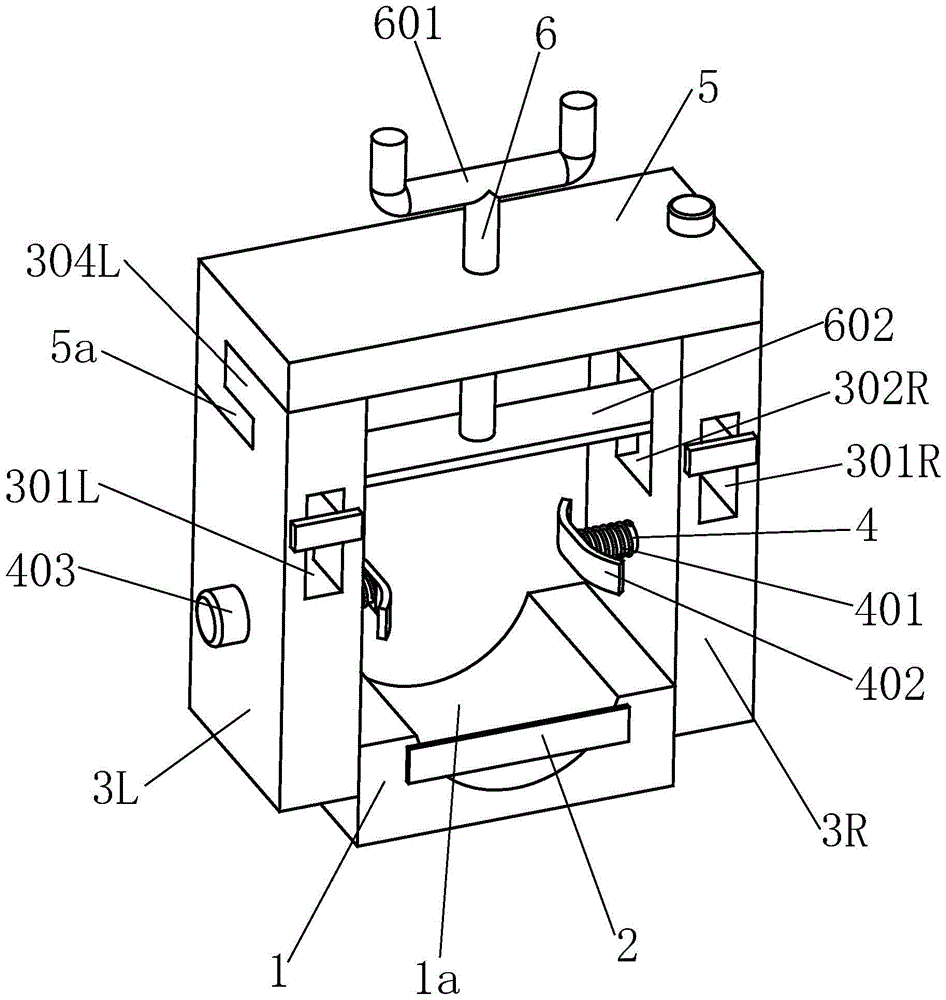
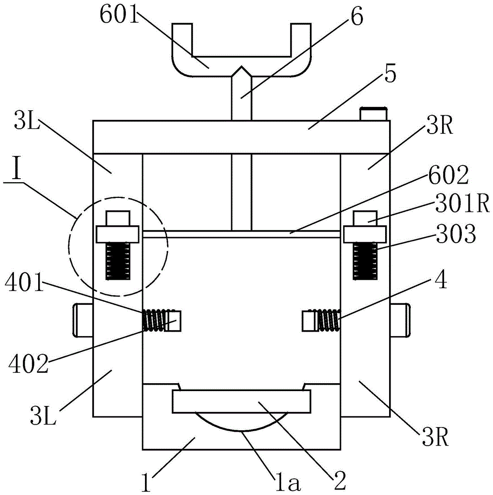
[0024] Such as Figure 1 to Figure 8 As shown, a drilling jig for a clutch master cylinder pump body includes a base 1. The middle part of the base 1 is provided with an arc-shaped concave surface that adapts to the shape of the lower end of the clutch master cylinder pump body. The left and right sides of the base 1 The left side plate 3L and the right side plate 3R are correspondingly provided with a sliding column 4 in the middle of the left side plate 3L and the right side plate 3R, and the sliding column 4 is located on the inner side of the left side plate 3L and the right side plate 3R. Parts are respectively covered with stage clips 401, and the inner ends of the spools 4 are fixed with sliding surfaces 402. While the sliding surfaces 40...


PUM


Abstract

The invention relates to a drilling clamp for a pump body of a clutch master pump. The drilling clamp comprises a base, wherein a left side plate and a right side plate are arranged on the left side and the right side of the base correspondingly and respectively, a lower meshing port is formed in the upper end of the left side plate, a rotating cover is hinged to the upper end of the right side plate, a threaded rod penetrates through the middle of the rotating cover in a thread connection manner, a handle is arranged at the upper end of the threaded rod, and an upper meshing port matched with the lower meshing port is formed in the left end of the rotating cover. According to the drilling clamp, the rotating cover and the left side plate are combined through the upper meshing port and the lower meshing port, and the rotating cover cannot shake vertically; by means of arranged sliding columns, compressed springs and sliding surfaces, the pump body of the clutch master pump can automatically return under the action of the compressed springs on two sides; the left side and the right side of a press frame are supported by corresponding springs respectively, the levelness of the press frame is guaranteed, the press frame is matched with the sliding columns, the compressed springs and the sliding surfaces for use, the pump body of the clutch master pump can be correctly placed in a three-dimensional and omnibearing manner, and the drilling accuracy is guaranteed.

Description

technical field [0001] The invention relates to the technical field of jigs, in particular to a jig for drilling holes in a pump body of a clutch master cylinder. Background technique [0002] The clutch master cylinder is the part connected to the clutch pedal and connected to the clutch booster through the oil pipe. The function is to collect the pedal travel information and realize the separation of the clutch through the action of the booster. Clutches and clutch master cylinders are easily damaged under bad driving habits, such as excessive use, heavy loads and frequent start-ups. People's driving safety. [0003] The clamping method of the clutch master cylinder commonly used in the prior art during processing is as follows: a left baffle and a right baffle are respectively provided on the left and right sides of the arc surface base, and a positioning column is provided on the upper end of the left baffle, so The upper end of the right baffle is hingedly connected ...

Claims


Application Information

Patent Timeline
Patent Type & Authority Patents(China)
IPC IPC(8): B23Q3/06
CPCB23Q3/062B23Q2703/10
Inventor 夏坤财
Owner 无锡市奥森塑化电子有限公司
Learn More