Pin puller

A technology of a pin puller and a screwed part is applied in the field of the pin puller, which can solve the problems of complicated operation, time-wasting, inconvenient replacement, etc.

Inactive Publication Date: 2014-12-03
FU TAI HUA IND SHENZHEN +1
View PDF8 Cites 6 Cited by
  • Summary
  • Abstract
  • Description
  • Claims
  • Application Information

AI Technical Summary

Problems solved by technology

The above-mentioned operation of replacing the tie rod is relatively cum

Method used


Image

  • Pin puller
  • Pin puller
  • Pin puller

Examples


Embodiment Construction

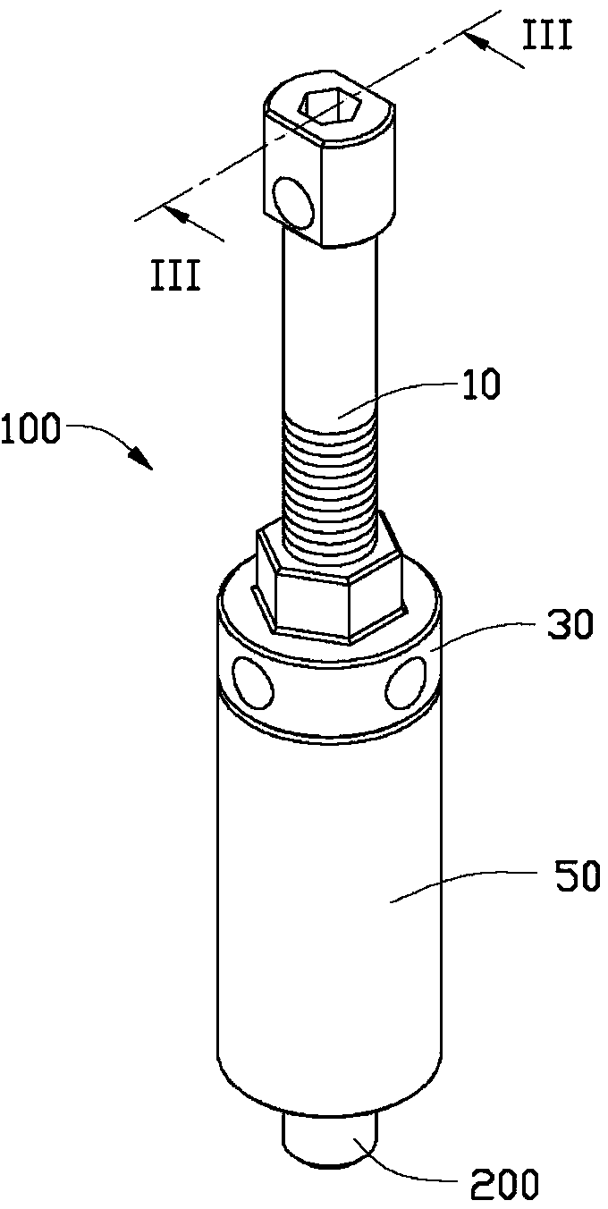
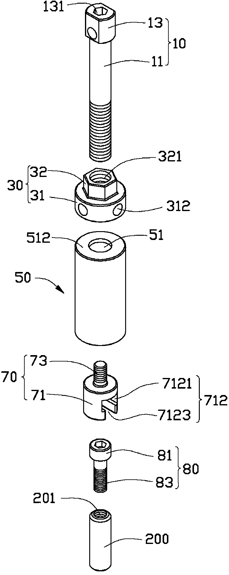
[0014] see figure 1 and figure 2 , the pin puller 100 according to the first embodiment of the present invention is used to remove the cylindrical pin 200 with internal thread. In this embodiment, the internally threaded cylindrical pin 200 is used to connect two workpieces (not shown in the figure), and the internally threaded cylindrical pin 200 is provided with a threaded hole 201 . The pin puller 100 includes a pull rod 10 , a limiting member 30 , a supporting sleeve 50 , a connecting member 70 and a locking member 80 .

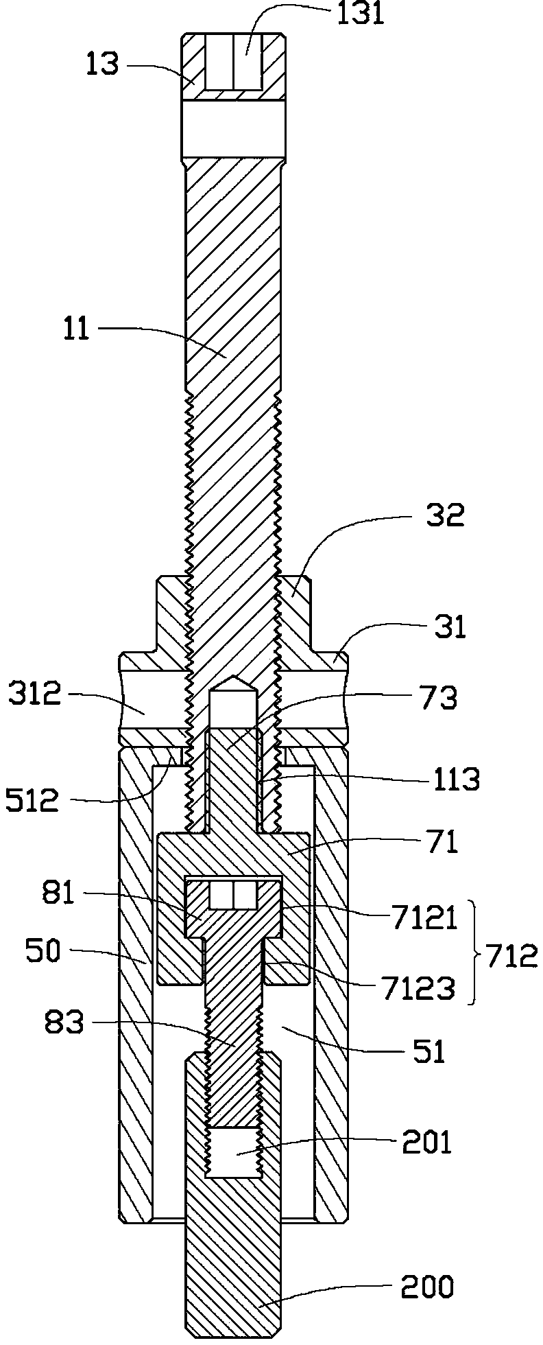
[0015] Please also see figure 2 , the tie rod 10 is roughly in the shape of a stepped cylinder, which includes a threaded portion 11 and an anti-rotation portion 13 protruding from one end of the threaded portion 11 . The threaded portion 11 is roughly cylindrical, and the end of the threaded portion 11 away from the anti-rotation portion 13 is provided with a fastening hole 113 (see image 3 ). An anti-rotation hole 131 is defined on an end of the...


PUM


Abstract

A pin puller comprising a pull rod, a limiting member, and a supporting sleeve. The pull rod comprising a threaded portion, and the limiting member is screwed on the threaded portion. The supporting sleeve defining a receiving through hole, and the threaded portion movably passing through the receiving hole thereby the supporting sleeve can be movably sleeved on the threaded portion and limited by the limiting member. One end of the threaded portion can be received in the receiving hole defining a stepped hole. The pin puller further comprising a locking member, the locking member can be detachably latched into the stepped hole, and partially protruding from the threaded portion.

Description

technical field [0001] The invention relates to a pin puller. Background technique [0002] In the process of disassembling the cylindrical pin with internal thread, a pin puller is generally used for disassembly. The pin puller includes a support sleeve, a limit piece and a pull rod. There is a locking hole on the support sleeve, and the limit piece is screwed to the locking hole of the support sleeve. The pull rod includes a guide part and a fixed part and a screw joint part respectively protruding from the two ends of the guide part. The guide part is movable. The ground is threaded on the limit piece, the screw connection part is screwed with the cylindrical pin with internal thread, and a bearing is installed between the fixed part and the limit piece. When disassembling the cylindrical pin with internal thread, firstly, one end of the threaded part of the pull rod is screwed with the cylindrical pin with internal thread; then, turn the stopper with a wrench so that t...

Claims


Application Information

Patent Timeline
IPC IPC(8): B25B27/02
CPCB25B27/062B25B27/20B25B27/023B25B27/04Y10T29/53883
Inventor 黄建明何长学管洪利
Owner FU TAI HUA IND SHENZHEN
Why Eureka
Try Eureka