Barrel plating device for hinge plating

A barrel plating and hinge technology, applied in the electrolytic process and electrolytic components, etc., can solve the problems of inability to observe the hinge plating condition, troublesome use, vibration displacement of the basket, etc., to prevent vibration displacement, good observation effect, The effect of enhancing usability

Inactive Publication Date: 2014-12-03
SUZHOU AOLIN HARDWARE
View PDF6 Cites 1 Cited by
  • Summary
  • Abstract
  • Description
  • Claims
  • Application Information

AI Technical Summary

Problems solved by technology

[0002] As we all know, the hinge is also known as the hinge, and the official name is the hinge. It is often composed of two folds. One of the indispensable links in the production of hinges, the electroplating method of hinges mainly adopts barrel plating; the existing barrel plating devices for hinge electroplating include barrel plating tanks and brackets, and motors and transmission gears are arranged on the brackets. The barrel plating tank is provided with an electrolyte and a placement basket, the placement basket is installed at the output end of the transmission gear, the interior of the placement basket is provided with a placement groove, and the side wall of the placement basket is provided with a material inlet, a material outlet and an electrolyte inlet. The outlet is provided with a feed cover at the material inlet, a discharge cover is provided at the discharge port, an electrolyte cover is provided at the inlet and outlet of the electrolyte, and multiple channels are arranged on the electrolyte cover. holes; it is found in the use of this barrel plating device for hinge electroplating that when the motor, the transmission gear and the placement basket are connected and driven to rotate the placement basket, it will bring large mechanical vibration and influence, which will cause the overall placement basket to vibrate and shift Therefore, it is often necessary to readjust the position of the basket, which is troublesome to use; moreover, it cannot effectively observe the electroplating condition of the hinge during the electroplating process inside the basket

Method used


Image

  • Barrel plating device for hinge plating

Examples


Embodiment Construction

[0011] The specific implementation manners of the present invention will be further described in detail below in conjunction with the accompanying drawings and embodiments. The following examples are used to illustrate the present invention, but are not intended to limit the scope of the present invention.

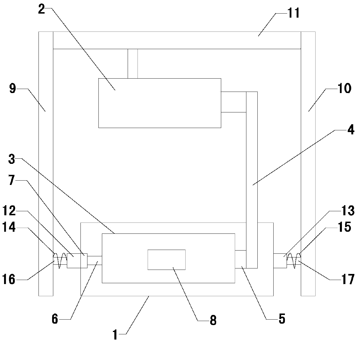
[0012] Such as figure 1 As shown, the barrel plating device for hinge electroplating of the present invention includes a barrel plating tank 1 and a bracket, a motor 2 is arranged on the bracket, an electrolyte solution and a placement basket 3 are arranged in the barrel plating bath, and a placement tank is arranged inside the placement basket , the side wall of the basket is provided with a material inlet, a material outlet, and an electrolyte inlet and outlet, and a material inlet cover is provided at the material inlet, and a material outlet cover is provided at the outlet, and the electrolyte inlet and outlet An electrolyte cover is arranged at the place, and a plura...


PUM


Abstract

The invention relates to the technical field of hinge processing equipment, and particularly relates to a barrel plating device for hinge plating. The barrel plating device for the hinge plating can be better observed, prevents the vibration displacement and enhances the practicability as far as possible. The barrel plating device comprises a barrel plating groove, a support frame and a driving belt, wherein the support frame is provided with a motor; the barrel plating groove is internally provided with an electrolytic solution and a placement basket, the placement basket is internally provided with a placement groove, the side wall of the placement groove is provided with a feed opening, a discharge opening, an electrolytic solution inlet and an electrolytic solution outlet, and a feed shield cover is arranged on the feed opening; two ends of the placement basket are provided with a universal driving shaft and a driven shaft respectively, the barrel plating groove is internally provided with a ball bearing, the outer wall of the barrel plating groove is provided with a reinforcing rib, and a damping spring is arranged between the reinforcing rib and the support frame; the side wall of the placement basket is provided with a viewing port, and an organic glass is arranged on the viewing port.

Description

technical field [0001] The invention relates to the technical field of hinge processing equipment, in particular to a barrel plating device for hinge electroplating. Background technique [0002] As we all know, the hinge is also known as the hinge, and the official name is the hinge. It is often composed of two folds. One of the indispensable links in the production of hinges, the electroplating method of hinges mainly adopts barrel plating; the existing barrel plating devices for hinge electroplating include barrel plating tanks and brackets, and motors and transmission gears are arranged on the brackets. The barrel plating tank is provided with an electrolyte and a placement basket, the placement basket is installed at the output end of the transmission gear, the interior of the placement basket is provided with a placement groove, and the side wall of the placement basket is provided with a material inlet, a material outlet and an electrolyte inlet. The outlet is provid...

Claims


Application Information

Patent Timeline
IPC IPC(8): C25D17/20
Inventor 贺卿
Owner SUZHOU AOLIN HARDWARE
Why Eureka
Try Eureka