Bone anchor and deployment device therefor

a deployment device and anchor technology, applied in the field of bone anchors, can solve the problems of hairline fractures, many deficiencies of the type of anchors, and easy dislocation of the anchor, so as to reduce the chance of the anchor dislocation, enhance the fixation of the tissue, and increase the interference strength

Inactive Publication Date: 2006-07-11
INNOVASIVE DEVICES
View PDF135 Cites 205 Cited by
  • Summary
  • Abstract
  • Description
  • Claims
  • Application Information

AI Technical Summary

Benefits of technology

[0015]In other aspects of the invention, an external surface of the expandable sleeve and / or the rivet has one or more annular ribs, threads or protrusions. These increase the strength of the interference fits between the rivet and the sleeve, as well as between the sleeve and the bone, thereby reducing the chances that the anchor will dislodge. The washer can likewise include ridges, teeth or other protrusions that enhance fixation of the tissue upon deployment.
[0016]In still other aspects of the invention, the bone anchor includes a housing which is frangibly coupled to the expandable sleeve via breakable flanges. The housing, which can be used to affix the anchor to the delivery device, can also protect and store the rivet prior to deployment. During deployment, the head of the rivet breaks the flanges of the housing, thereby freeing the housing from the anchor.

Problems solved by technology

Anchors of this type, however, had many deficiencies.
For example, they were prone to coming out of the bone, particularly in cases where patients were relatively active.
In addition, because the anchors were hammered directly into the bone, deployment was difficult and could sometimes result in hairline fractures.
If this is not done, then sufficient contact may not be achieved with the surrounding tissue to hold the tissue in place.
Understandably, achieving such placement can be difficult when the anchors are placed endoscopically.
In addition to the foregoing, the force required to deploy a conventional bone anchor often makes deployment problematic.
Driving a tack or nail-like anchor into bone, for example, is difficult if the surgeon does not have adequate leverage on the bone to counterbalance the force of impact.

Method used


Image

  • Bone anchor and deployment device therefor
  • Bone anchor and deployment device therefor
  • Bone anchor and deployment device therefor

Examples


Embodiment Construction

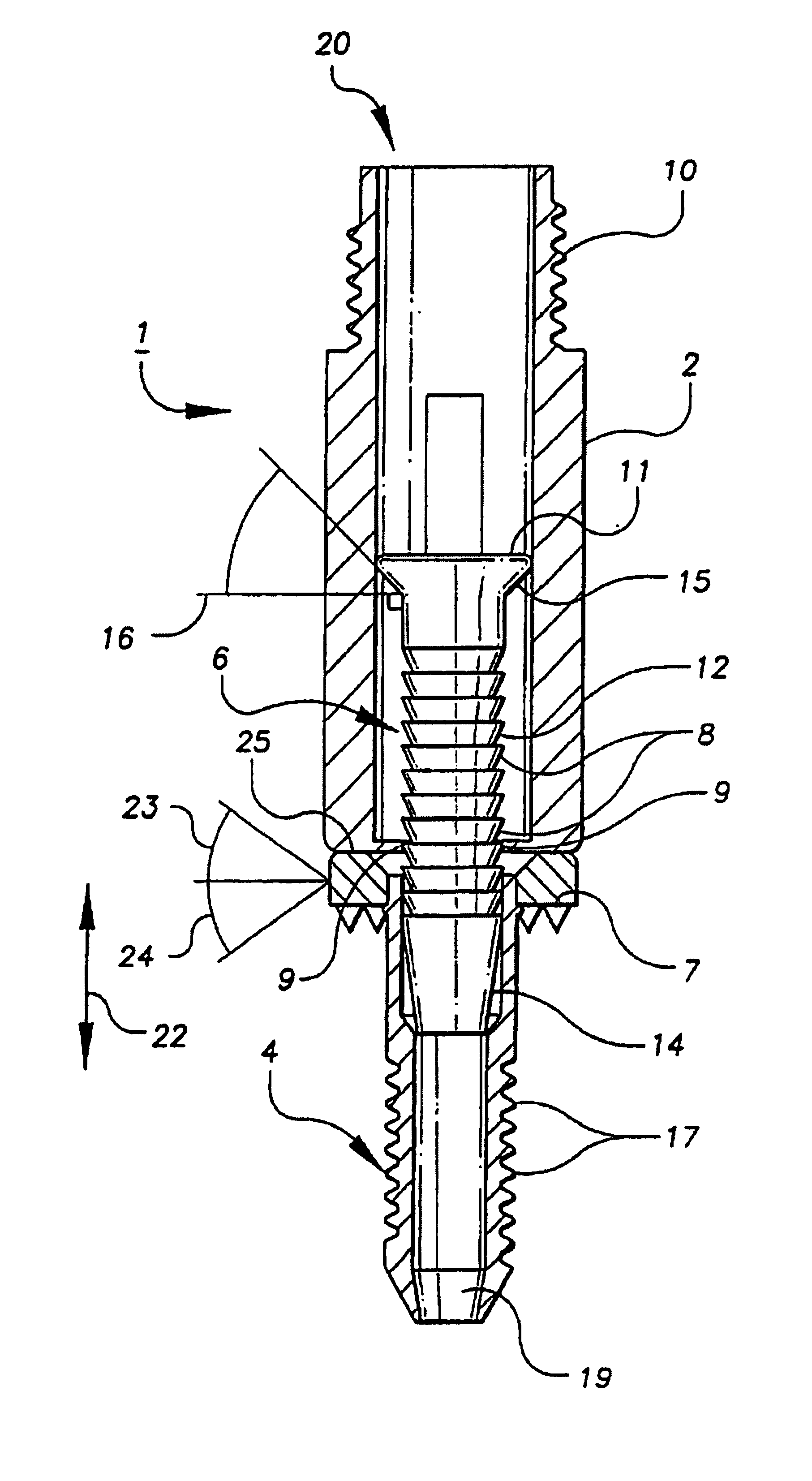
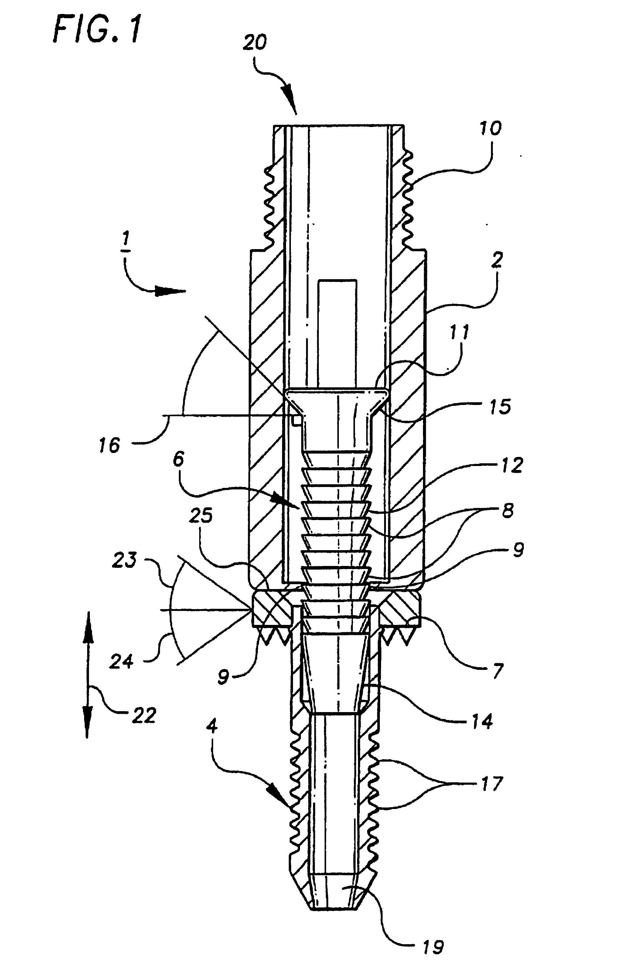
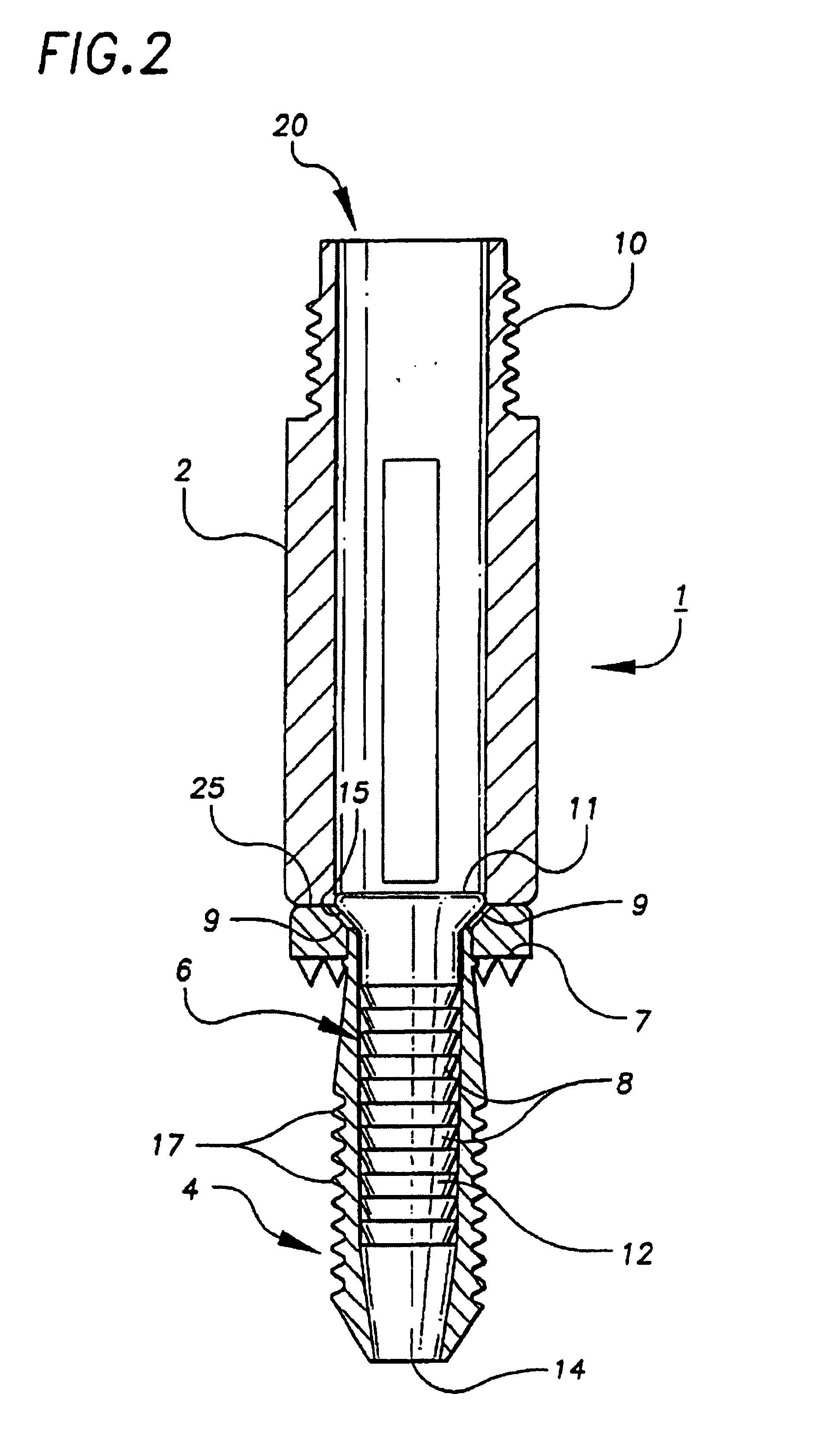
[0031]FIGS. 1 and 2 are close-up, cut-away views of a bone anchor according to the present invention. As shown in FIG. 1, bone anchor 1 includes housing 2, expandable 5 sleeve 4, rivet 6, floating washer 7, breakable flanges 9, and threading 10. In preferred embodiments of the invention, some or all of these components are made of a bioabsorbable material which dissolves in a patient's body over a period of time leaving little or no trace. Alternatively, bone anchor 1 may be made of other biocompatible materials, such as conventional plastics or the like.

[0032]Rivet 6 is comprised of head 11, elongate body 12, tapered tip 14, and a centerbore (not shown) running therethrough. Head 11 is located at the proximal end of rivet 6 and has a diameter which is greater than that of either elongate body 12 or tapered tip 14. Head 11 also includes undersurface 15. Undersurface 15 can be formed with a spherical radius or, alternatively, angled relative to a longitudinal axis of the elongate bod...


PUM


Abstract

A rivet-like bone anchor has a floating washer at its head that can adapt to an angled bone surface and, thereby, better secure a tissue thereto. The anchor includes a rivet, an expandable sleeve, and a washer. The rivet includes a head and an elongate body having proximal and distal ends, the head being mounted on the proximal end of the elongate body. The expandable sleeve has an inner bore adapted to receive the rivet body. The washer “floats” at a proximal end of the sleeve. As the rivet is inserted into sleeve, the sleeve expands into an interference fit with the bone. The head of the rivet, moreover, forces the floating washer into contact with the tissue at an angle that conforms to that of the underlying bone surface. A deployment tool permits the anchor to be deployed without application of unnecessary counterforce. The tool includes an outer tube, the distal end of which can hold the anchor housing, e.g., via a screw fit. A rod, which is slidably disposed within the bore of the tube, can be used to push the rivet into the expandable sleeve so that the sleeve expands into the bone, so that the floating washer is forced into position against the bone surface, and so that anchor is broken away from the housing. This can be effected, for example, by squeezing the distal ends of the outer tube and the rod together, e.g., in the manner that the end of a syringe is squeezed.

Description

REFERENCE TO RELATED APPLICATIONS[0001]This application claims the benefit of priority of and is a continuation-in-part of U.S. application Ser. No. 08 / 595,772, filed on Feb. 2, 1996 now U.S. Pat. No. 5,968,044 and of application Ser. No. 08 / 814,149, filed on Mar. 10, 1997 now U.S. Pat. No. 5,911,721 and, thereby, of U.S. application Ser. No. 08 / 163,130 (now U.S. Pat. No. 5,725,529) filed on Dec. 6, 1993 and, thereby, of U.S. application Ser. No. 07 / 765,445 (now U.S. Pat. No. 5,268,001) filed on Sep. 25, 1991 and, thereby, of U.S. application Ser. No. 07 / 588,025 (now abandoned) filed on Sep. 25, 1990.BACKGROUND OF THE INVENTION[0002]The present invention is directed to a bone anchor for attaching tissue to bone, and to a device for deploying such an anchor in bone. More specifically, the invention is directed to a bone anchor which employs a “floating” washer that conforms to the angle of the bone surface to hold tissue in place, and to a deployment device having a plunger-like conf...

Claims


Application Information

Patent Timeline
Patent Type & Authority Patents(United States)
IPC IPC(8): A61B17/56A61B17/00A61B17/04A61F2/08
CPCA61F2/0811A61F2/0805A61B2017/00004A61B2017/0403A61B2017/0409A61B2017/0424A61B2017/044Y10S606/916A61F2002/0835A61F2002/0858A61F2002/0888
Inventor JOHANSON, MARK A.RICE, JOHNHART, RICKEYNICHOLSON, JAMES
Owner INNOVASIVE DEVICES
Why Eureka
Try Eureka