
bidirectional gear motor

A two-way gear and motor technology, used in rotary piston engines, rotary or oscillating piston engines, machines/engines, etc., can solve the problem of inability to withstand radial forces and bending moments, increase the starting torque of gear motors, and difficult assembly of seals and other problems, to improve the working pressure and mechanical efficiency, improve the clearance of the axial fit, and improve the high-temperature starting performance.

Active Publication Date: 2016-09-07
HEFEI CHANGYUAN HYDRAULICS
View PDF7 Cites 0 Cited by
  • Summary
  • Abstract
  • Description
  • Claims
  • Application Information

AI Technical Summary

Problems solved by technology

[0004] 1) if Figure 10 As shown, the driving gear 8 and the driven gear 10 of the existing structure of the 32-125mL / r gear motor adopt 4 modules and 13 teeth, the center distance is 56mm, and the gear pressure angle is the current GB / T1356-1988 "Involute Linear cylindrical gear reference tooth shape "standard gear, the pressure angle is 20°, due to the large overlap coefficient and backlash when the gear meshes, the gear motor is easy to heat the hydraulic oil during the working process, the volumetric efficiency is low, and the service life is short ;
[0005] 2) if Figure 10 As shown, the driving gear 8 and the front cover 6 in the existing structure are simple straight-through structures, which cannot withstand the axial force, radial force and bending moment caused by factors such as installation errors, resulting in premature failure of the gear motor;
[0006] 3) if Figure 10 As shown, the front cover 6, the housing 7 and the rear cover 20 in the existing structure are three-stage structures, the processes of the pump body and the rear cover are scattered, and it is difficult to ensure the dimensional accuracy of the mounting holes of each component at the same time with the existing processing level
At the same time, the dispersion of the process and the multiple clamping and processing of parts and components lead to a large overall cumulative error of the product, resulting in an increase in the radial load of the motor bearing, an increase in the overall friction torque, and greater difficulty in the assembly of seals, which increases the The starting torque of the gear motor;
[0007] 4) if Figure 10 As shown, the shaft sleeve in the existing structure adopts the traditional split type shaft sleeve, and two independent shaft sleeves 21 are respectively arranged on the driving gear shaft 9 and the driven gear shaft 11, and the shaft sleeves 21 are arranged axially in the housing 7 under pressure. When floating, it is difficult for the two bushings to be consistent, resulting in poor sealing of the end face, and it is difficult to guarantee the volumetric efficiency of the gear motor during normal operation;
The disadvantages of this structure are: ①The overall sealing performance is poor, the leakage at the gap cannot be controlled, and the friction coefficient is large; ②The overall installation and operability are poor. The suitability is poor, and it is easy to cause problems such as misalignment and pressure ring; ③ In order to ensure volumetric efficiency, the traditional gear motor first considers increasing the compression of the seal to provide sealing performance, which cannot take into account the low starting torque of the gear motor
When the pressure area of ​​the bidirectional motor is continuously switched, it is impossible to ensure a suitable gear motor axial fit clearance under the condition of ensuring the sealing, and it is impossible to ensure the low starting torque of the gear motor under the condition of ensuring the gear motor axial fit clearance

Method used


Image

  • bidirectional gear motor
  • bidirectional gear motor
  • bidirectional gear motor

Examples


Embodiment Construction

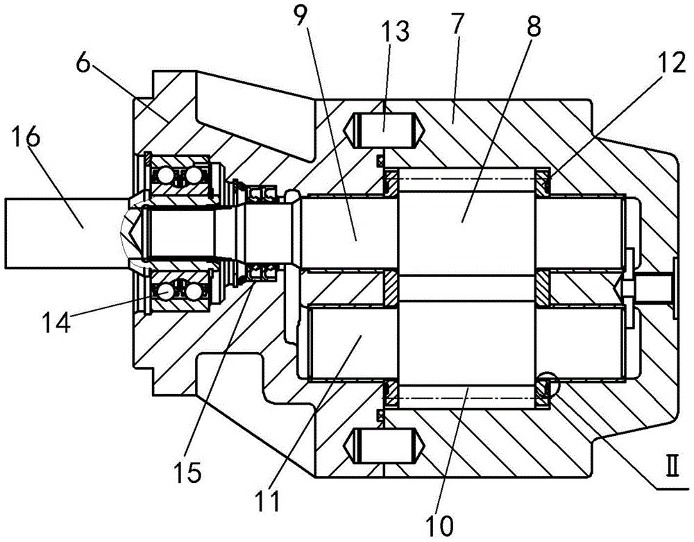
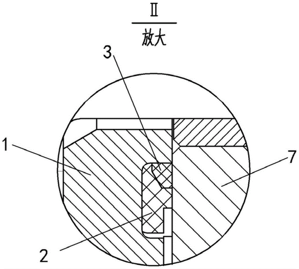
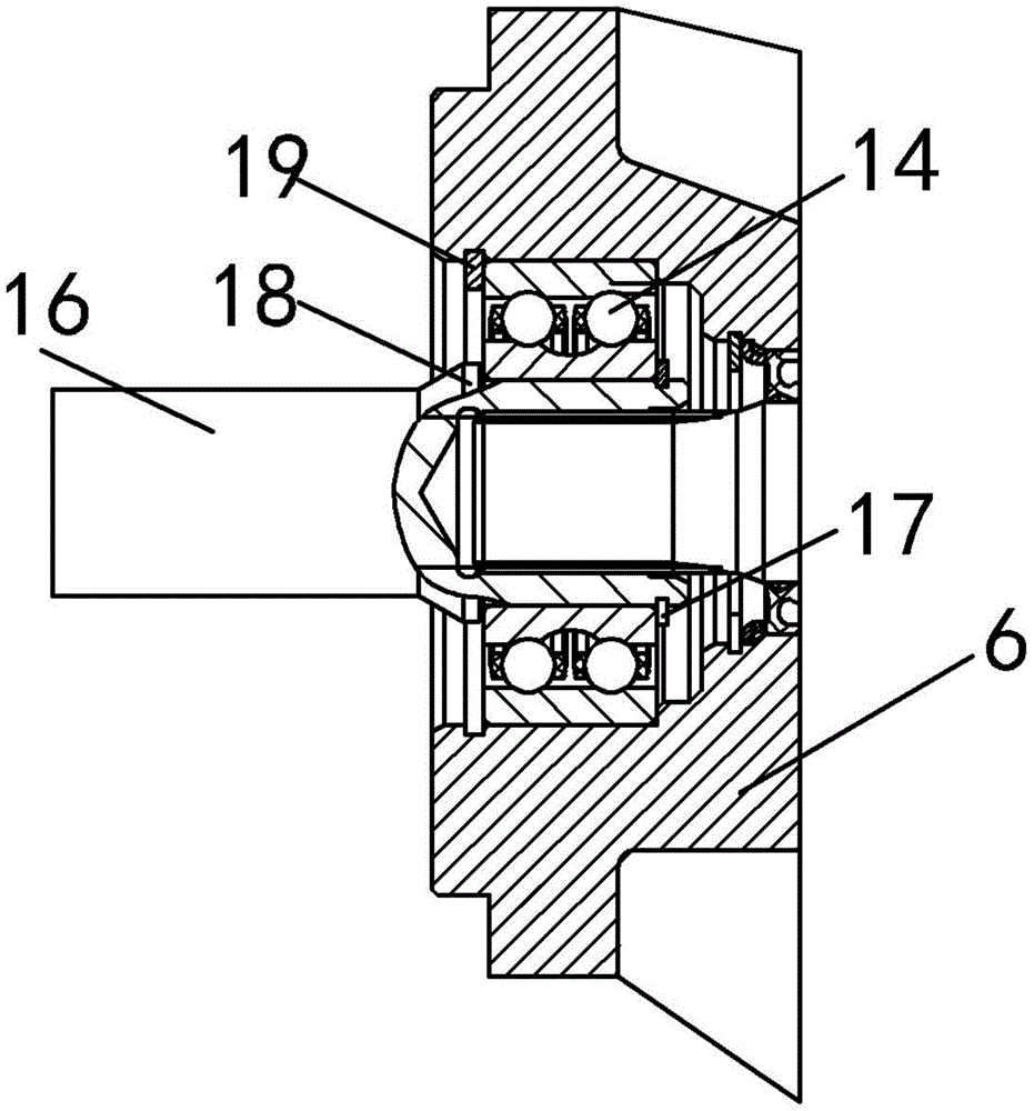
[0047] see attached picture figure 1 ~ attached Figure 9 , the bidirectional gear motor of the present invention includes a front cover 6, a housing 7, a driving gear 8, a driving gear shaft 9, a driven gear 10, a driven gear shaft 11 and a side plate 12; the housing 7 includes a left side An open trough cavity, the driving gear 8, the driving gear shaft 9, the driven gear 10, the driven gear shaft 11 and the side plate 12 are all arranged in the housing 7; the front cover 6 is fixedly arranged on the left end face of the housing 7, and close the left opening of the groove cavity; the left end of the driving gear shaft 9 passes through the front cover 6 and protrudes from the left end of the front cover 6 ; The front cover 6 is provided with a stepped inner cavity, and the driving gear shaft 9 passes through the stepped inner cavity; the left end cavity of the stepped inner cavity is set as a bearing cavity, and the stepped inner cavity The cavity at the right end of the c...


PUM


Abstract

The invention discloses a bidirectional gear motor, which comprises a front cover, a casing, a driving gear, a driving gear shaft, a driven gear, a driven gear shaft and a side plate; , the driving gear shaft, the driven gear, the driven gear shaft and the side plate are all arranged in the casing; the front cover is fixedly arranged on the left end surface of the casing, and closes the left opening of the groove cavity; the driving gear The left end of the shaft passes through the front cover and protrudes from the left end of the front cover; the front cover is provided with a stepped inner cavity, and the driving gear shaft passes through the stepped inner cavity; the left end cavity of the stepped inner cavity is set as a bearing cavity, The right end cavity of the stepped inner cavity is set as a sealing cavity; a bearing is set in the bearing cavity, and an oil seal is set in the sealing cavity, and both the bearing and the oil seal are sleeved on the driving gear shaft. The bidirectional gear motor of the present invention has the advantages of compact structure, high working pressure, low noise, good starting performance at high temperature, long service life, wide application range and the like.

Description

technical field [0001] The invention relates to a side plate of a gear motor, in particular to a bidirectional gear motor. Background technique [0002] As the power component of the hydraulic system, the gear motor is widely used in the hydraulic system of construction machinery such as loaders, excavators, and cranes at home and abroad. The gear motor has the characteristics of simple structure, small size, light weight, strong self-priming force, and insensitivity to oil pollution. It is widely used in the field of hydraulic technology, especially in the construction machinery industry. [0003] The existing 32-125mL / r gear motor has the following problems in practical application due to structural limitations: [0004] 1) if Figure 10 As shown, the driving gear 8 and the driven gear 10 of the existing structure of the 32-125mL / r gear motor adopt 4 modules and 13 teeth, the center distance is 56mm, and the gear pressure angle is the current GB / T1356-1988 "Involute Line...

Claims


Application Information

Patent Timeline
Patent Type & Authority Patents(China)
IPC IPC(8): F03C2/08
Inventor 周亚东郑金朝黄翠萍
Owner HEFEI CHANGYUAN HYDRAULICS
Learn More