
An on-orbit debugging system and method for realizing the penetration profile of a solar magnetic field telescope

A technology of solar magnetic field and debugging system, applied in the field of optics, can solve the problems such as the decrease of the measurement accuracy of the solar magnetic field through profile detection and calibration, and the inability to realize the telescope, which is conducive to accurate evaluation and problem solving, and shortens the cycle of putting into use. , to ensure the effect of measurement accuracy

Inactive Publication Date: 2016-10-05
NAT ASTRONOMICAL OBSERVATORIES CHINESE ACAD OF SCI
View PDF6 Cites 0 Cited by
  • Summary
  • Abstract
  • Description
  • Claims
  • Application Information

AI Technical Summary

Problems solved by technology

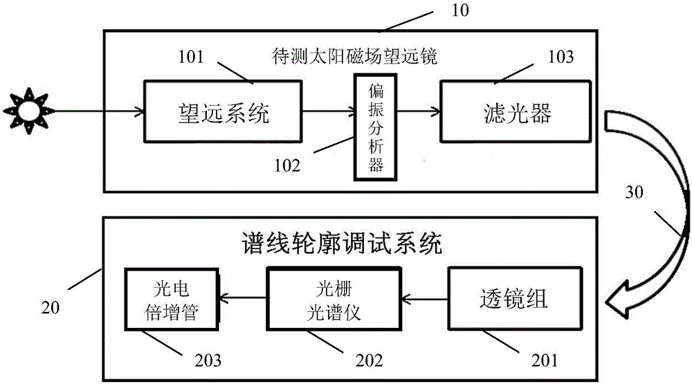
[0004] The technical problem to be solved by the present invention is to provide an on-orbit debugging system and method for realizing the transmission profile of the solar magnetic field telescope, so as to solve the problem that the original detection and calibration of the entire telescope transmission profile and the measurement of the solar magnetic field are affected by the environment. Problems that affect the decline in measurement accuracy

Method used


Image

  • An on-orbit debugging system and method for realizing the penetration profile of a solar magnetic field telescope
  • An on-orbit debugging system and method for realizing the penetration profile of a solar magnetic field telescope
  • An on-orbit debugging system and method for realizing the penetration profile of a solar magnetic field telescope

Examples


Embodiment Construction

[0029] The following examples are only used to illustrate the technical solution of the present invention more clearly, but not to limit the protection scope of the present invention. Certain terms are used, for example, in the description and claims to refer to particular components. Those skilled in the art should understand that hardware manufacturers may use different terms to refer to the same component. The specification and claims do not use the difference in name as the way to distinguish components, but use the difference in function of the components as the criterion for distinguishing. The subsequent description of the specification is a preferred implementation mode for implementing the present invention, but the description is for the purpose of illustrating the general principles of the present invention, and is not intended to limit the scope of the present invention. The scope of protection of the present invention should be defined by the appended claims.

...


PUM


Abstract

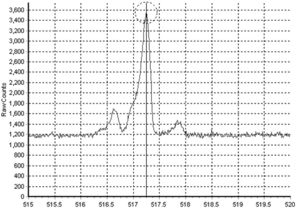
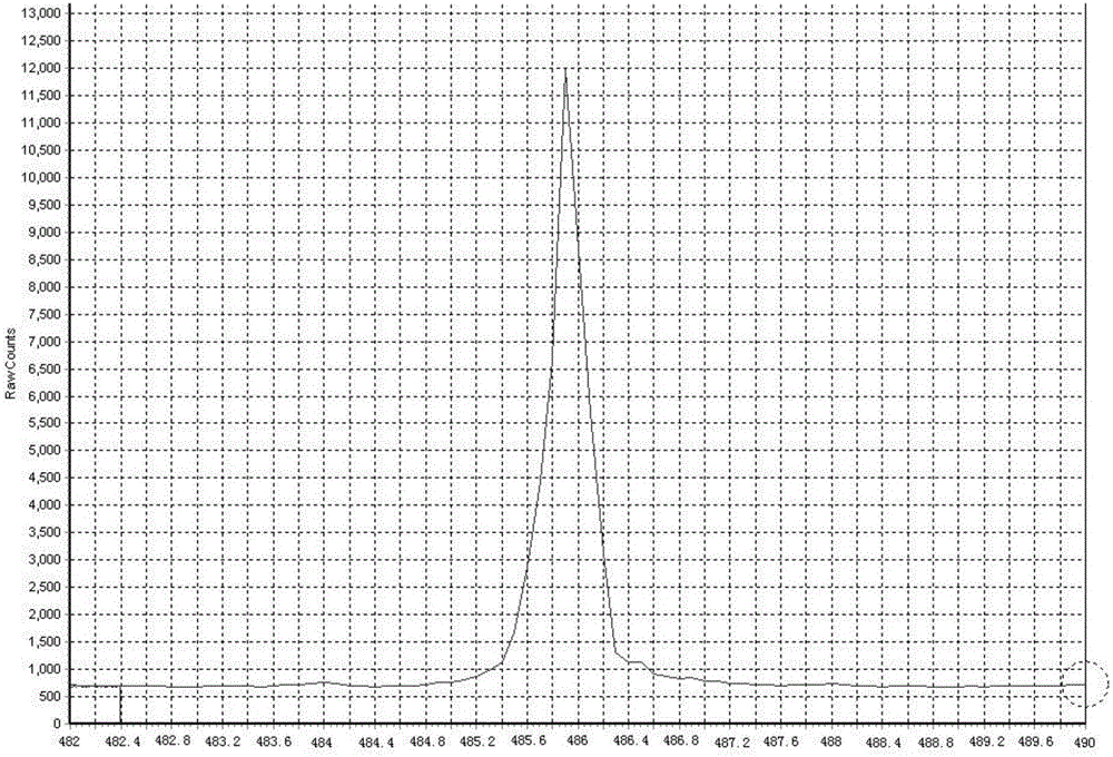
The invention discloses an on-orbit debugging system and method for realizing the transmission profile of a solar magnetic field telescope. A spectrometer and a photomultiplier tube are coaxially arranged in sequence for spectral line profile debugging system, wherein an optical fiber bundle is connected between the output end of the optical filter and the input end of the lens group, and the optical filter includes at least one crystal stage, respectively adjust the orientation of each crystal stage in the optical filter, so that the light source output from the solar magnetic field telescope to be measured is guided through the optical fiber bundle and sequentially passes through the lens group imaging, grating spectrometer profile scanning and photoelectric multiplication The spectral line profile output from the amplified signal of the tube is displayed on the computer. The invention solves the problems that the original optical system cannot judge the transmission profile of the use state of the entire telescope and the measurement accuracy of the solar magnetic field decreases.

Description

technical field [0001] The invention relates to the field of optical technology, in particular to an on-orbit debugging system and method for realizing the transmission profile of a solar magnetic field telescope. Background technique [0002] The violent eruption in the solar strong magnetic field area is often accompanied by a large amount of high-energy radiation and charged particle flow, which has an important impact on aerospace safety, short-wave communication, near-Earth meteorology and human living environment. The study of the solar magnetic field has long been a solar research Theme of. The solar magnetic field telescope is a kind of astronomical telescope. It is a key instrument for the core research of solar physics. The solar magnetic field telescope was installed in the Huairou Solar Observatory of Beijing Astronomical Observatory in 1985. Study the solar magnetic field, velocity field and related solar physical phenomena. [0003] The birefringent filter is...

Claims


Application Information

Patent Timeline
Patent Type & Authority Patents(China)
IPC IPC(8): G01M11/02
Inventor 孙英姿王东光
Owner NAT ASTRONOMICAL OBSERVATORIES CHINESE ACAD OF SCI
Learn More