Tool deflection modeling method for multi-axis machining system

A technology of multi-axis machining and modeling method, applied in general control system, control/adjustment system, simulator, etc., can solve the problem of aggravated tool wear and even edge chipping, is not suitable for attitude-changing machining, and does not fully consider multi-axis machining systems issues of flexibility

Active Publication Date: 2014-12-03
HUAZHONG UNIV OF SCI & TECH
View PDF0 Cites 19 Cited by
  • Summary
  • Abstract
  • Description
  • Claims
  • Application Information

AI Technical Summary

Problems solved by technology

[0004] 1. There are only studies on tool deviation for "three-axis machining", such as: Landon, Y., Segonds, S., Lascoumes, P., and Lagarrigue, P., 2004, "Tool Positioning Error (TPE )Characterisation in Milling,"Int.J.Mach.Tools Manuf.,44(5),pp.457–464, using the three-axis machining experimental model, the obtained deviation is only applicable to the three-axis, not applicable to more Offset calculation for widely used multi-axis plus systems
[0005] 2. Some are only for relatively simple milling of ball end cutters or flat bottom cutters, such as: Dépincé, P., and J.Y., 2006, “Active Integration of Tool Deflection Effects in End Milling.Part1.Prediction of Milled Surfaces,” Int.J.Mach.Tools Manuf.,46(9),pp.937–944., only for flat bottom knife machining , not suitable for high-strength steel processing, otherwise it is easy to aggravate tool wear and even chipping; Dow, T.A., Miller, E.L., and Garrard, K., 2004, "Tool Force and Deflection Compensation for Small Milling Tools," Precis.Eng ., 28, pp.31–45., only for ball-end cutter machining, the change of tool attitude cannot optimize the contact state between the tool envelope surface and the design surface, and the processing efficiency is low
[0006] 3. The flexibility of each part of the multi-axis machining system is not fully considered
In order to simplify modeling, the existing technology either regards the tool as a rigid body, or regards the spindle or tool holder as a rigid body, especially the flexibility of the transmission shaft of the processing system is usually not considered for research, so that the calculated flexibility cannot Objectively reflect the true flexibility of the processing system, resulting in a small calculation deviation
For example: Liang, S.Y., and Zheng, L., 1998, “Analysis of End Milling Surface Error Considering Tool Compliance,” ASME J.Manuf.Sci.Eng.120(1), 207–210, Dow, T.A., Miller, E.L., and Garrard, K., 2004, "Tool Force and Deflection Compensation for Small Milling Tools," Precis.Eng., 28, pp.31–45, none of the above documents considered the flexibility of tool holders and machine tool axes, There is a large error in the obtained tool deviation
[0007] 4. Calculation of the undeformed cutting thickness of the cutting edge of the tool. By decomposing the feed vector into the feed in the axial and radial directions of the tool, the feed vector of the blade element is obtained and the undeformed cutting thickness is obtained by further calculation. This calculation method has the following defects: first, it is not suitable for machining with variable attitude; second, it is related to cutting parameters such as feed, and the calculation is complicated and difficult to understand; third, it is not directly related to the tool attitude, and it is impossible to establish subsequent deviation and The relationship between tool attitude

Method used


Image

  • Tool deflection modeling method for multi-axis machining system
  • Tool deflection modeling method for multi-axis machining system
  • Tool deflection modeling method for multi-axis machining system

Examples


Embodiment Construction

[0084] The present invention will be further described below in conjunction with the accompanying drawings and specific embodiments.

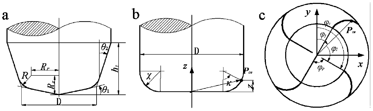
[0085] The tool deviation modeling method of the multi-axis machining system provided by the present invention includes five coordinate systems: tool coordinate system (t), machine tool coordinate system (m), tool contact local coordinate system (p), ellipsoid Coordinate system (e), workpiece coordinate system (w), different algebraic quantities or physical quantities are respectively established in their relevant coordinate systems, but in further derivation to be expressed in other coordinate systems, it needs to be transformed to In other coordinate systems, therefore, the modeling method of the present invention includes multiple coordinate transformations.

[0086] The method for modeling the tool deviation of the multi-axis machining system provided by the present invention includes the following steps S1-S10:

[0087] S1: Establish the ...


PUM


Abstract

The invention discloses a tool deflection modeling method for a multi-axis machining system. The tool deflection modeling method includes establishing a new non-deformable cutting thickness model, and a cutting force prediction model of arc-tool variable-posture milling by the vector method; establishing a flexibility model of a machine transmission shaft by the equivalent column method and a comprehensive flexibility model of the machining system by force ellipsoid method and coordinate system transformation; finally utilizing the cutting force model in the process of variable-posture machining and the flexibility model at the tail end of the multi-axis machining system to obtain a tool deflection model. In the tool deflection modeling method, the non-deformable cutting thickness model of a new tool cutting blade and the comprehensive flexibility model of the multi-axis machining system are used to obtain a more accurate tool deflection change law during machining, so that the tool postures during multi-axis machining and machining parameters such as feed speed and spindle revolving speed are optimized, tool deflection is controlled, and quality of machined surfaces of workpiece is improved.

Description

technical field [0001] The present invention relates to a modeling method of tool deviation in a multi-axis machining system, in particular to a tool deviation modeling method based on a cutting force model and a multi-axis machining system comprehensive stiffness model, which is suitable for five-axis arc milling cutters The field of milling technology. Background technique [0002] In five-axis milling, the tool has a larger reachable space relative to the surface of the workpiece, which caters to the needs of complex curved surface processing. Through the tool attitude planning, the interference collision between the tool, the workpiece and the fixture can be avoided, and the machining efficiency can be improved by improving the contact characteristics between the tool envelope surface and the workpiece design surface. However, critical parts in aerospace, such as compressor wheels, landing gear, and engine casings, not only have complex contoured surfaces, but also ultr...

Claims


Application Information

Patent Timeline
Patent Type & Authority Applications(China)
IPC IPC(8): G06F19/00G05B19/404
Inventor 彭芳瑜段现银江兰兰朱泽润闫蓉李斌
Owner HUAZHONG UNIV OF SCI & TECH
Why Eureka
Try Eureka