Control rod drive mechanism and its connection with control rods

A driving mechanism and control rod technology, which is used in the control of nuclear reactions, reactors, and greenhouse gas reduction, etc., can solve the problems of tripping, the disconnection of the control rod and the end of the detachable joint, etc., to ensure stable clamping and reduce accidents. The effect of the risk of tripping

Active Publication Date: 2017-07-14
CHINA NUCLEAR POWER TECH RES INST CO LTD +1
View PDF1 Cites 0 Cited by
  • Summary
  • Abstract
  • Description
  • Claims
  • Application Information

AI Technical Summary

Problems solved by technology

However, when there is an unexpected working condition, such as a large impact load, the upper end of the control rod will squeeze the end and move upward. In severe cases, the control rod may be disengaged from the end of the detachable joint, resulting in accidental tripping

Method used


Image

  • Control rod drive mechanism and its connection with control rods
  • Control rod drive mechanism and its connection with control rods
  • Control rod drive mechanism and its connection with control rods

Examples


Embodiment Construction

[0031] The preferred embodiments of the present invention will be described below in conjunction with the accompanying drawings.

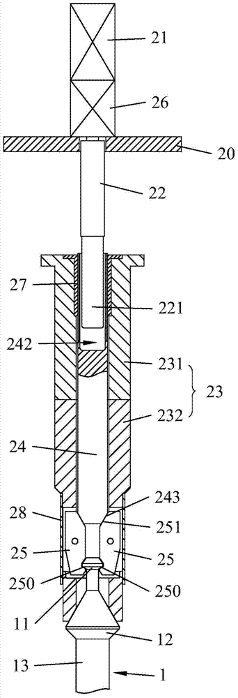
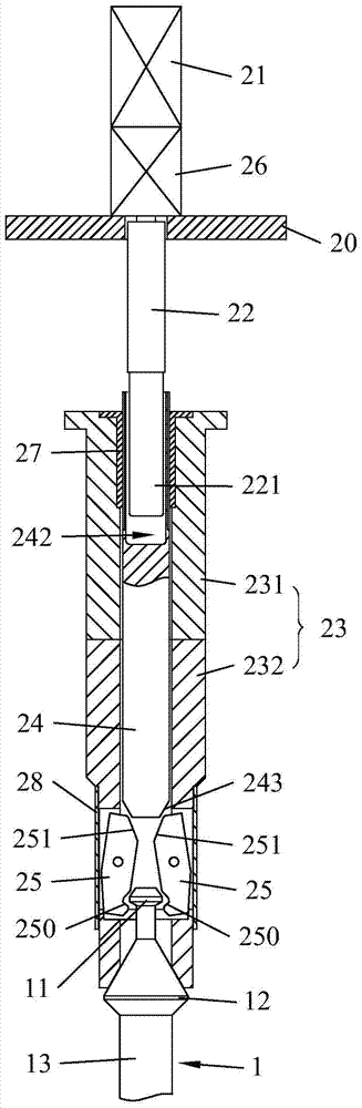
[0032] like figure 2As shown, the present invention provides a control rod drive mechanism, including a machine base 20, a motor 21, a transmission rod 22, a hollow shaft 23, a push rod 24 and at least three grippers 25; the hollow shaft 23 and the The base 20 is fixedly connected, the inner wall of the hollow shaft 23 is provided with a threaded area, the side wall of the push rod 24 is provided with external threads, and the push rod 24 is accommodated in the hollow shaft 23 and connected to the The threaded area is threaded, the motor 21 is fixed on the base 20 and drives the transmission rod 22 to rotate, the lower end of the transmission rod 22 extends into the hollow shaft 23 and is in contact with the push rod 24 The handle 25 is pivotally connected to the side wall of the hollow shaft 23, and the lower end of the handle 25 forms a hook su...


PUM


Abstract

The invention discloses a control rod driving mechanism which comprises a machine seat, a motor, a transmission rod, a hollow shaft, an ejector rod and at least three grippers, wherein the hollow shaft is fixedly connected with the machine seat; the inner wall of the hollow shaft is provided with a thread area; the side wall of the ejector rod is provided with an external thread; the ejector rod is contained in the hollow shaft and is in threaded matched with the thread area; the motor is fixed on the machine seat and is used for driving the transmission rod to rotate; the lower end of the transmission rod extends into the hollow shaft and is connected with the ejector rod in a way of circumferential location; the grippers are pivoted on the side wall of the hollow shaft; a blocking hook surface which extends towards the central axis of the hollow shaft and is inclined downwards is formed on the lower end of each gripper; the upper ends of the grippers are pushed downwards by the ejector rod, and the blocking hook surfaces of the at least three grippers are driven to clamp a control rod together. The assembly and disassembly of the control rod driving mechanism and the control rod are convenient and fast, and the risk of releasing of the control rod can be effectively reduced. Correspondingly, the invention also provides a connecting way of the control rod driving mechanism and the control rod.

Description

technical field [0001] The invention belongs to the technical field of control rod driving mechanisms, in particular to a control rod driving mechanism capable of preventing accidental tripping. Background technique [0002] The start-stop and power control of the nuclear reactor core are all realized by the control rod drive mechanism driving the control rods to move up and down into and out of the core, and the control rod drive mechanism and the control rods are connected by a certain structure. When a normal shutdown is required, the control rod drive mechanism gradually inserts the control rods into the fuel assemblies to stop the chain reaction; when an emergency shutdown is required, the control rod drive mechanism is disconnected from the control rods, and the control rods are quickly inserted into the fuel assemblies by their own gravity. [0003] like figure 1 As shown in , the upper end of the control rod 1 is formed with an upper gripping head 11 and a lower gri...

Claims


Application Information

Patent Timeline
Patent Type & Authority Patents(China)
IPC IPC(8): G21C7/12G21C7/14
CPCY02E30/30
Inventor 卢朝晖周建明吕永红王晓白冰
Owner CHINA NUCLEAR POWER TECH RES INST CO LTD
Why Eureka
Try Eureka