Passenger car frame clamp

A frame and fixture technology, which is applied to vehicle parts, manufacturing tools, auxiliary devices, etc., can solve the problems that affect the welding efficiency, the fixture cannot be adjusted in real time, and cannot meet the requirements, so as to achieve the effect of ensuring efficiency

Pending Publication Date: 2018-03-13
苏州友邦汽车底盘科技有限公司
View PDF6 Cites 0 Cited by
  • Summary
  • Abstract
  • Description
  • Claims
  • Application Information

AI Technical Summary

Problems solved by technology

The fixtures used in the welding of the vehicle frame in the prior art cannot be adjusted in real time according to the specific conditions on site, and cannot meet the welding requirements of some complicated situations, which affects the welding efficiency

Method used


Image

  • Passenger car frame clamp
  • Passenger car frame clamp
  • Passenger car frame clamp

Examples


Embodiment 1

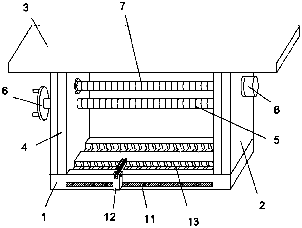
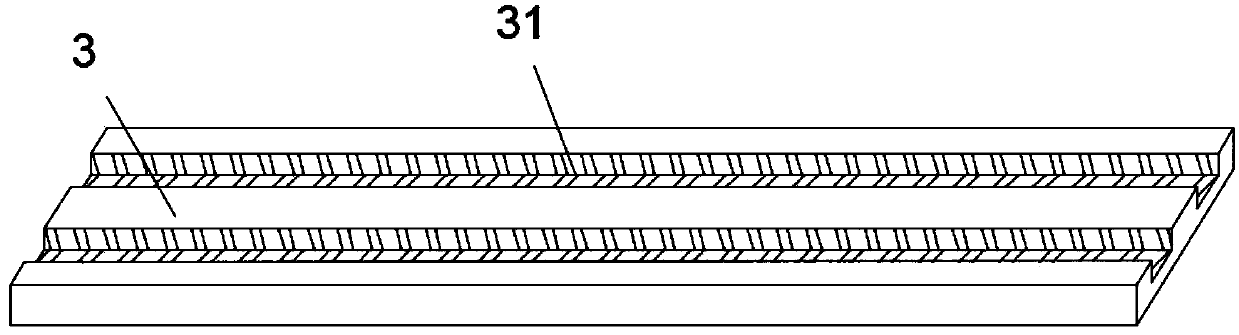
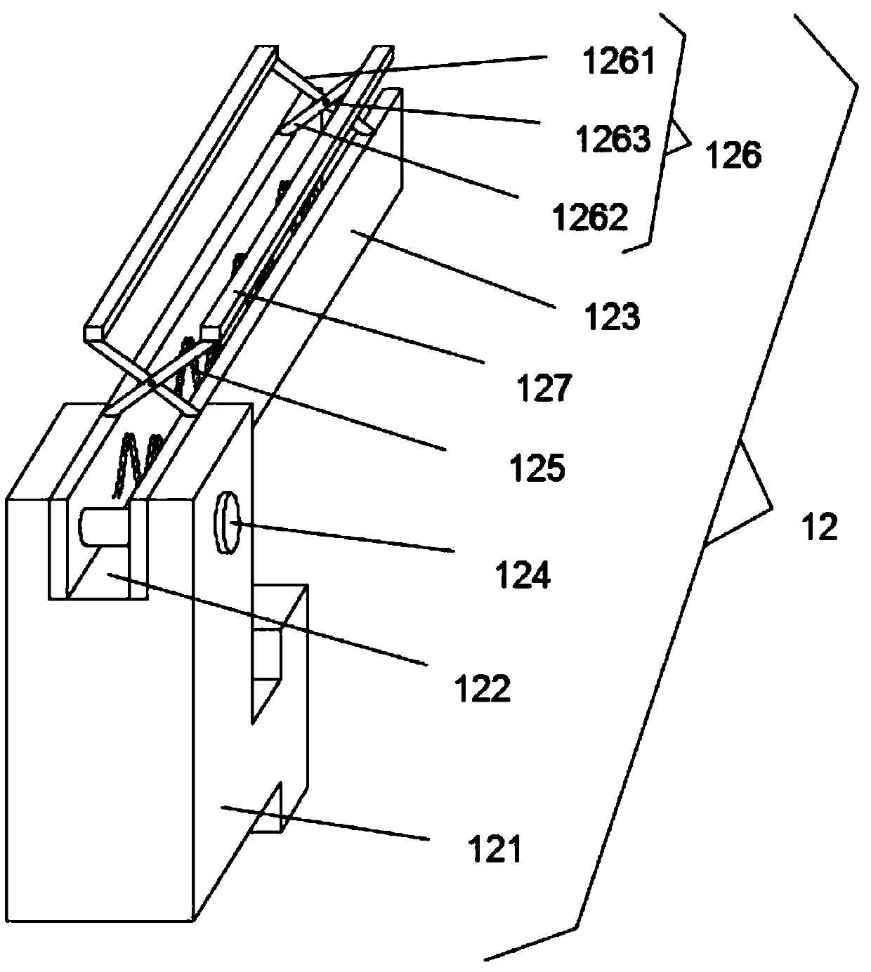
[0023] A passenger car frame clamp, comprising a base 1, a bar-shaped chute 11 is opened on the lower side of the front surface of the pedestal 1, and a positioning device 12 is slidably installed inside the bar-shaped chute 11, the base The upper surface of the base 1 is uniformly and horizontally provided with two first slide grooves 13, and the left and right sides of the upper surface of the base 1 are fixedly equipped with support plates 2, and the upper surface of the support plate 2 is fixedly equipped with a top plate 3, so The lower surface of the top plate 3 is provided with two second chute 31, and the two second chute 31 corresponds to the position of the two first chute 13 up and down, the first chute 13 and the second chute 31 There are two clamping plates 4 slidingly installed between them, and the outer surfaces of the two clamping plates 4 are closely attached to the support plate 2 on the same side, and the clamping plates 4 on both sides are used to clamp the...

Embodiment 2

[0029]A passenger car frame clamp, comprising a base 1, a bar-shaped chute 11 is opened on the lower side of the front surface of the pedestal 1, and a positioning device 12 is slidably installed inside the bar-shaped chute 11, the base The upper surface of the base 1 is uniformly and horizontally provided with two first slide grooves 13, and the left and right sides of the upper surface of the base 1 are fixedly equipped with support plates 2, and the upper surface of the support plate 2 is fixedly equipped with a top plate 3, so The lower surface of the top plate 3 is provided with two second chute 31, and the two second chute 31 corresponds to the position of the two first chute 13 up and down, the first chute 13 and the second chute 31 There are two clamping plates 4 slidingly installed between them, and the outer surfaces of the two clamping plates 4 are closely attached to the support plate 2 on the same side, and the clamping plates 4 on both sides are used to clamp the ...


PUM


Abstract

The invention discloses a passenger car frame clamp. A positioning device is arranged on the front surface of a base in a sliding mode, a top plate is fixedly arranged at the upper ends of supportingplates on the upper surface of the base, two clamping plates are arranged between first sliding grooves and second sliding grooves in a sliding mode, a first lead screw penetrates through the left supporting plate and the left clamping plate, and a second lead screw penetrates through the upper end of the right supporting plate and the right clamping plate. The positioning device can quickly clampa car frame, and controls the position of the right clamping plate through the positioning device, so that the stable clamping of the car frame is guaranteed, the clamping mode is suitable for various situations, real-time adjustment can be carried out according to the field specific conditions, the welding requirement of complex conditions is met, and the welding efficiency is guaranteed.

Description

technical field [0001] The invention relates to the technical field of clamps, in particular to a passenger car frame clamp. Background technique [0002] The frame is also called the girder. The base of the car is generally composed of two longitudinal beams and several cross beams. It is supported on the wheels through the suspension device, front axle, and rear axle. It has sufficient strength and rigidity to bear the load of the car and from the wheels. The function of the frame is to support and connect the various assemblies of the car, so that each assembly maintains a relatively correct position, and bears various loads inside and outside the car. The fixtures used in the welding of the vehicle frame in the prior art cannot be adjusted in real time according to the actual conditions on site, which cannot satisfy welding in some complicated situations, which affects the welding efficiency. Contents of the invention [0003] The object of the present invention is to...

Claims


Application Information

Patent Timeline
Patent Type & Authority Applications(China)
IPC IPC(8): B23K37/04
CPCB23K37/0443B23K2101/006
Inventor 王军宋毅
Owner 苏州友邦汽车底盘科技有限公司
Why Eureka
Try Eureka