

Method for improving machining efficiency of exhaust manifold air inlet flange
An air inlet flange, processing efficiency technology, applied in the direction of using gas flow cleaning methods, metal processing equipment, cleaning methods and utensils, etc., can solve the problems of reducing work efficiency, wasting a long time, inconvenient to use, etc. The effect of improving work efficiency and improving processing efficiency
- Summary
- Abstract
- Description
- Claims
- Application Information
AI Technical Summary
Problems solved by technology
Method used
Image

Examples
Embodiment
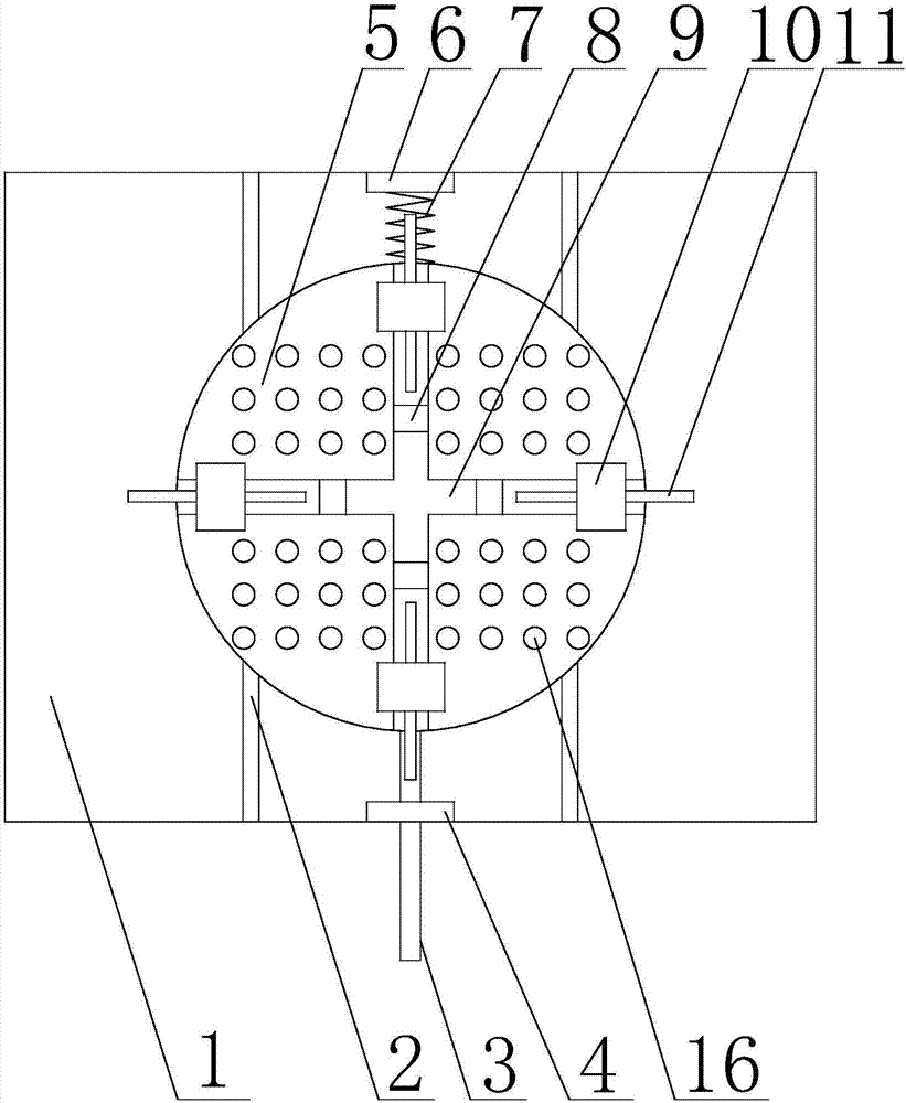
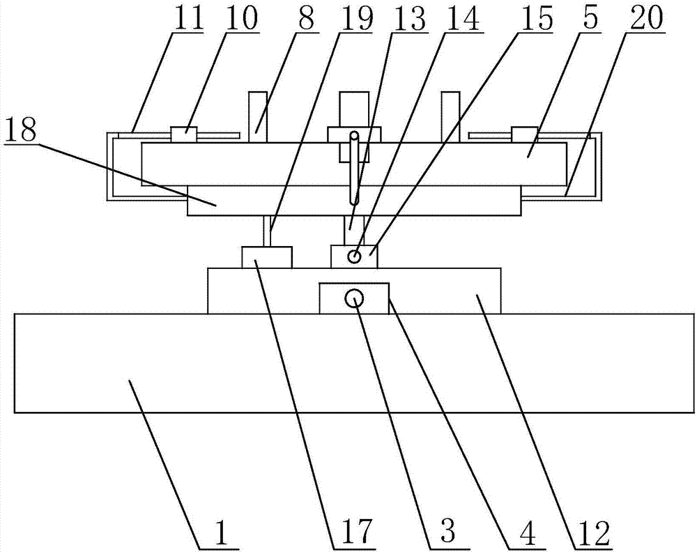
[0036] like Figure 1 to Figure 5 Shown, the present invention improves the method for the processing efficiency of exhaust manifold inlet flange,
[0037] Include the following steps:
[0038] 1) Place the flange to be processed on the top of the clamping disc 5;
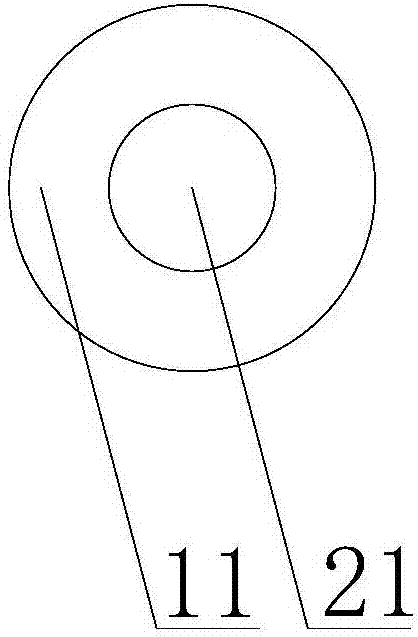
[0039] 2) Rotate the adjusting rod 11 in turn, the end of the adjusting rod 11 enters the air outlet channel 22 of the splint 8, and pushes the splint 8 to move in the groove 8, and fastens the flange to be processed;
[0040] 3) During the processing of the flange, the push rod 3 is rotated, and the push rod 3 pushes the mobile table 12 to move in the movable groove 2. At the same time, the threaded rod 14 is loosened, and the clamping disc 5 is rotated to process the flange flexibly;
[0041] 4) During the processing of the flange, the fan 17 is turned on, and the airflow generated by the fan 17 enters the windshield 18, and the airflow in the windshield 18 is blown into the groove 8 and the clamping plate 5, a...
PUM
 Abstract
Description
Claims
Application Information